Series 15i/150i - Model B Maintenance manual Page 153
Maintenance manual
B–63785EN/01
2. 15i SERIES HARDWARE
131
When the data server board is activated normally, the state of No. 10 is
set. This state is maintained until an error occurs.
LED display upon the occurrence of an error (STATUS)
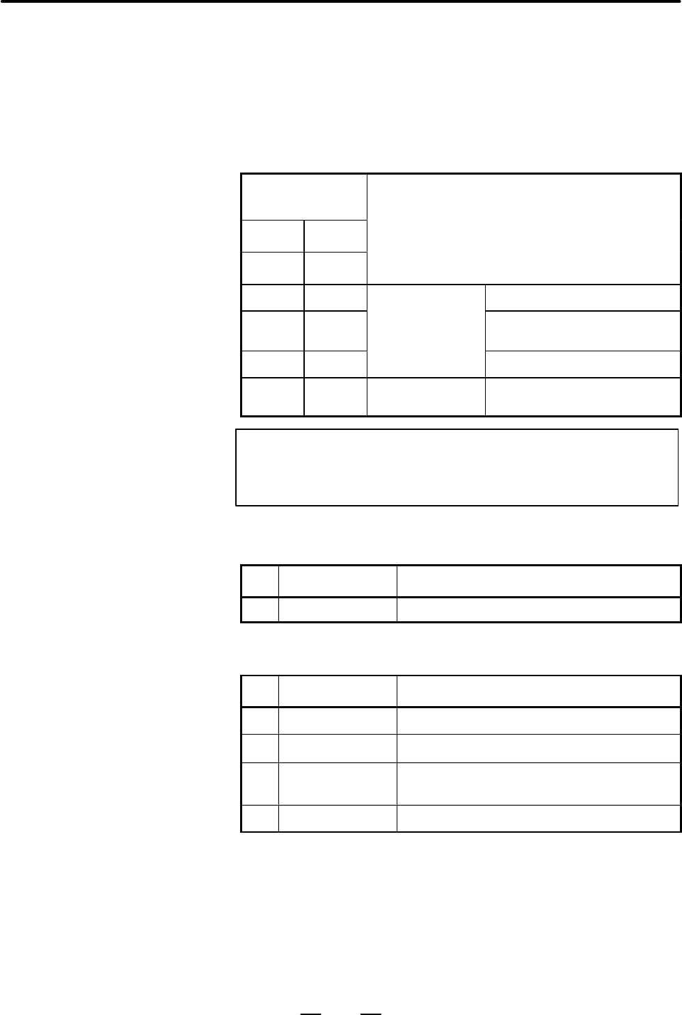
The STATUS LED alternately displays the LONG and SHORT patterns.
The LONG patterns are displayed long, and the SHORT patterns are
displayed short.
LED display
(STATUS)
LONG SHORT
Data server board status
4 3 2 1 4 3 2 1
J j j j j j j J
Failure in Ethernet
Reset
J j j j j j J j
board
General machine check exception,
bus error, address error, etc.
J J j j j j j J DRAM Parity
J J j j j j J j Failure in another
board
Other NMI
NOTE
If the LONG and SHORT patterns which are not listed above
are repeatedly displayed, contact FANUC.
LED display upon the occurrence of an error (alarm)
No. LED display Data server board state
1 Parity Alarm J A parity error occurred in memory on the Data server.
LED display for communication status
No. LED display Data server board state
1 RXLED J
Turned on when data is received.
2 TXLED J
Turned on when data is sent.
3 TPPIL J
Turned on when a connection with the hub is es-
tablished.
4 COLLED J
Turned on when a data collision occurs.
TPPIL : While this LED is off, communication is not being
performed. Connection to the hub may not have been made
normally. This LED will also be off when the power to the
hub is not turned on. When a connection with the hub is
established, this LED lights steadily.
COLLED : This LED lights frequently when there is a high level of
noise or traffic in Ethernet communication.
D STATUS LED display
(green) when an error
occurs
Contents Summary of Series 15i/150i - Model B Maintenance manual
- Page 1MAINTENANCE MANUAL B-63785EN/01
- Page 2• No part of this manual may be reproduced in any form. • All specifications and designs are subject to change without notice. The export of this product is subject to the authorization of the government of the country from where the product is exported. In this manual we have tried as much as possi
- Page 3SAFETY PRECAUTIONS This section describes the safety precautions related to the use of CNC units. It is essential that these precautions be observed by users to ensure the safe operation of machines equipped with a CNC unit (all descriptions in this section assume this configuration). CNC maintenanc
- Page 4SAFETY PRECAUTIONS B–63785EN/01 1 DEFINITION OF WARNING, CAUTION, AND NOTE This manual includes safety precautions for protecting the maintenance personnel (herein referred to as the user) and preventing damage to the machine. Precautions are classified into Warnings and Cautions according to their
- Page 5B–63785EN/01 SAFETY PRECAUTIONS 2 WARNINGS RELATED TO CHECK OPERATION WARNING 1. When checking the operation of the machine with the cover removed (1) The user’s clothing could become caught in the spindle or other components, thus presenting a danger of injury. When checking the operation, stand aw
- Page 6SAFETY PRECAUTIONS B–63785EN/01 WARNING 5. Ensure that the specified feedrate is appropriate for the intended operation. Generally, for each machine, there is a maximum allowable feedrate. The appropriate feedrate varies with the intended operation. Refer to the manual provided with the machine to d
- Page 7B–63785EN/01 SAFETY PRECAUTIONS 3 WARNINGS RELATED TO REPLACEMENT WARNING 1. Always turn off the power to the CNC and the main power to the power magnetics cabinet. If only the power to the CNC is turned off, power may continue to be supplied to the serve section. In such a case, replacing a unit ma
- Page 8SAFETY PRECAUTIONS B–63785EN/01 4 WARNINGS RELATED TO PARAMETERS WARNING 1. When machining a workpiece for the first time after modifying a parameter, close the machine cover. Never use the automatic operation function immediately after such a modification. Instead, confirm normal machine operation
- Page 9B–63785EN/01 SAFETY PRECAUTIONS 5 WARNINGS AND NOTES RELATED TO DAILY MAINTENANCE WARNING 1. Memory backup battery replacement When replacing the memory backup batteries, keep the power to the machine (CNC) turned on, and apply an emergency stop to the machine. Because this work is performed with th
- Page 10SAFETY PRECAUTIONS B–63785EN/01 WARNING 2. Absolute pulse coder battery replacement When replacing the memory backup batteries, keep the power to the machine (CNC) turned on, and apply an emergency stop to the machine. Because this work is performed with the power on and the cabinet open, only those
- Page 11B–63785EN/01 SAFETY PRECAUTIONS WARNING 3. Fuse replacement Before replacing a blown fuse, however, it is necessary to locate and remove the cause of the blown fuse. For this reason, only those personnel who have received approved safety and maintenance training may perform this work. When replacing
- Page 12
- Page 13B–63785EN/01 PREFACE PREFACE Description of 1.Display and operation this manual This chapter covers those items, displayed on the screen, that are related to maintenance. A list of all supported operations is also provided at the end of this chapter. 2.Hardware This chapter covers hardware–related i
- Page 14PREFACE B–63785EN/01 Applicable models This manual can be used with the following models. The abbreviated names may be used. Pruduct name Abbreviation FANUC Series 15i–MB 15i–MB Series 15i FANUC Series 150i–MB 150i–MB Series 150i NOTE Some function described in this manual may not be applied to some
- Page 15B–63785EN/01 Table of Contents SAFETY PRECAUTIONS . . . . . . . . . . . . . . . . . . . . . . . . . . . . . . . . . . . . . . . . . . . . . . . . . . s–1 PREFACE . . . . . . . . . . . . . . . . . . . . . . . . . . . . . . . . . . . . . . . . . . . . . . . . . . . . . . . . . . . . . . . . p–1 1. SCR
- Page 16Table of Contents B–63785EN/01 1.16.3 How to Begin the “BIOS SET–UP” . . . . . . . . . . . . . . . . . . . . . . . . . . . . . . . . . . . . . . . . . . . . . . . . . . . 102 1.16.4 How to End the “BIOS SET–UP” . . . . . . . . . . . . . . . . . . . . . . . . . . . . . . . . . . . . . . . . . . . . .
- Page 17B–63785EN/01 Table of Contents 2.5.3.1 Removing the board . . . . . . . . . . . . . . . . . . . . . . . . . . . . . . . . . . . . . . . . . . . . . . . . . . . . . . . . . 170 2.5.3.2 Mounting the board . . . . . . . . . . . . . . . . . . . . . . . . . . . . . . . . . . . . . . . . . . . . . . . . .
- Page 18Table of Contents B–63785EN/01 3.2.1 Output of Part Programs . . . . . . . . . . . . . . . . . . . . . . . . . . . . . . . . . . . . . . . . . . . . . . . . . . . . . . . . . . . . 235 3.2.2 Output of System Parameters . . . . . . . . . . . . . . . . . . . . . . . . . . . . . . . . . . . . . . . . .
- Page 19B–63785EN/01 Table of Contents 4.3.4.5 Counter screen (COUNTR) . . . . . . . . . . . . . . . . . . . . . . . . . . . . . . . . . . . . . . . . . . . . . . . . . . . 299 4.3.4.6 Keep relay screen (KEEPRL) . . . . . . . . . . . . . . . . . . . . . . . . . . . . . . . . . . . . . . . . . . . . . . . .
- Page 20Table of Contents B–63785EN/01 7.10.3 Alarm SP0220 (no Spindle Amplifier) . . . . . . . . . . . . . . . . . . . . . . . . . . . . . . . . . . . . . . . . . . . . . . . . . 392 7.10.4 Alarm SP0221 (Illegal Spindle Motor Number) Alarm SP0996 (Illegal Spindle Parameter Setting) . . . . . . . . . . . .
- Page 21B–63785EN/01 Table of Contents APPENDIX A. BOOT SYSTEM . . . . . . . . . . . . . . . . . . . . . . . . . . . . . . . . . . . . . . . . . . . . . . . . . . . . . . . . 429 A.1 OVERVIEW . . . . . . . . . . . . . . . . . . . . . . . . . . . . . . . . . . . . . . . . . . . . . . . . . . . . . . . . . .
- Page 22
- Page 23B–63785EN/01 1. SCREEN INDICATIONS AND OPERATIONS 1 SCREEN INDICATIONS AND OPERATIONS 1.1 FUNCTION KEYS AND SOFT KEYS . . . . . . . . . . . . 2 1.2 SCREEN INDICATIONS AT POWER ON . . . . . . . . . 10 1.3 DIAGNOSIS FUNCTION . . . . . . . . . . . . . . . . . . . . . . . 11 1.4 CNC STATE INDICATIONS .
- Page 241. SCREEN INDICATIONS AND OPERATIONS B–63785EN/01 1.1 FUNCTION KEYS AND SOFT KEYS 1.1.1 (1) Press a function key on the MDI panel to show the soft keys for Indication Procedure chapter selection related to the function. for General Screens OFFSET POS PROG SETTING CUSTOM SYSTEM MESSAGE GRAPH (2) Pres
- Page 25B–63785EN/01 1. SCREEN INDICATIONS AND OPERATIONS 1.1.2 Use a function key to select the corresponding function. Types of Function Keys The following function keys are provided for the MDI panel. Press this key to show an actual position screen. POS Press this key to show a program screen. PROG Pres
- Page 261. SCREEN INDICATIONS AND OPERATIONS B–63785EN/01 1.1.4 To select a function with the corresponding soft key, press the function Function Selection menu key first to set soft keys to a function selection key state, and then press the desired function selection key. Keys Function selection is allowed
- Page 27B–63785EN/01 1. SCREEN INDICATIONS AND OPERATIONS 1.1.5 Use function selection keys to select items (functions). Chapter Selection Keys Each item is further divided into subitems (chapters). Use a chapter selection key to select the corresponding subitem (chapter). To select a chapter, press the CHA
- Page 281. SCREEN INDICATIONS AND OPERATIONS B–63785EN/01 1.1.5.2 Program Function key on the MDI panel Soft keys PROG PRO- CHAP- GRAM TER (1) (2) (3) (4) (5) (6) (7) (8) (9) (10) (11) (12) (13) (14) (15) (16) (17) (18) (19) No. Chapter menu Description (1) TEXT Selects a screen for indicating the contents
- Page 29B–63785EN/01 1. SCREEN INDICATIONS AND OPERATIONS 1.1.5.3 Offset/setting Function key on the MDI panel Soft keys OFFSET OFFSET CHAP- SET- SET- TING TING TER (1) (2) (3) (4) (5) (6) (7) (8) (9) (10) (11) (12) (13) (14) (15) (16) (17) (18) (19) (21) (22) (23) (24) (25) (26) (27) (28) (29) No. Chapter
- Page 301. SCREEN INDICATIONS AND OPERATIONS B–63785EN/01 1.1.5.4 System Function key on the MDI panel Soft keys SYS- SYS- CHAP- TEM TEM TER (1) (2) (3) (4) (5) (6) (7) (8) (9) (10) (11) (12) (13) (14) (15) (16) (17) (18) (19) (21) (22) (23) (24) (25) (26) (27) (28) (29) No. Chapter menu Description (1) PAR
- Page 31B–63785EN/01 1. SCREEN INDICATIONS AND OPERATIONS 1.1.5.5 Messages Function key on the MDI panel Soft keys MES- MES- CHAP- SAGE SAGE TER (1) (2) (3) (4) (5) (6) (7) (8) (9) (10) No. Chapter menu Description (1) ALARM Selects an alarm message screen. (2) OPERATOR Selects an operator message screen. (
- Page 321. SCREEN INDICATIONS AND OPERATIONS B–63785EN/01 1.2 The test results of hardware (RAM and ROM), and the check results of control software and file data are indicated on the screen at power on. SCREEN INDICATIONS AT FANUC SERIES 15I F010A POWER ON COPYRIGHT(C) FANUC LTD 1997–1999 Series and edition
- Page 33B–63785EN/01 1. SCREEN INDICATIONS AND OPERATIONS 1.3 If an error occurs, or if a machine operation stops for some reason such as an external–signal wait state without an error and it seems as if an error DIAGNOSIS occurs, it is necessary to check the cause from the internal CNC state and FUNCTION a
- Page 341. SCREEN INDICATIONS AND OPERATIONS B–63785EN/01 D Cause for not starting #7 #6 #5 #4 #3 #2 #1 #0 1005 OTH RPO JMD Bit Name Internal state when “1” is indicated #0 JMD DI and DO signals are incorrect in a manual numeric command (*1). #1 RPO DI and DO signals are incorrect in repositioning for tool
- Page 35B–63785EN/01 1. SCREEN INDICATIONS AND OPERATIONS D Alarm classification The diagnostic data 1007 and 1008 indicates classification information of a generated alarm. When the alarm is released, the data becomes “0.” #7 #6 #5 #4 #3 #2 #1 #0 1007 PW IO PC OT SV SW Bit Name Internal state when “1” is i
- Page 361. SCREEN INDICATIONS AND OPERATIONS B–63785EN/01 D Cause of turning off of the cycle start lamp #7 #6 #5 #4 #3 #2 #1 #0 1011 HLD STP MOD ALM RST ERS RRW ESP Bit Name Internal state when “1” is indicated #0 ESP During emergency stop #1 RRW The reset and rewind signal is “1.” #2 ERS The external rese
- Page 37B–63785EN/01 1. SCREEN INDICATIONS AND OPERATIONS D Serial spindle The diagnostic data 1500 to 1505 indicates serial–spindle information. #7 #6 #5 #4 #3 #2 #1 #0 1500 SALMI CALM CMER CER SNER FRER CRER [Data type] Bit spindle type Bit Name Internal state when “1” is indicated #0 CRER A CRC error occ
- Page 381. SCREEN INDICATIONS AND OPERATIONS B–63785EN/01 1563 Spindle motor temperature information [Data type] Integer axis [Unit of data] °C [Valid data range] 0 to 255 Displays the temperature of the winding of the αi spindle motor when the αi spindle I/F is used. The temperature at which overheating oc
- Page 39B–63785EN/01 1. SCREEN INDICATIONS AND OPERATIONS D Digital servo alarm The diagnostic data 3014 and 3015 indicates alarm information when an alarm is generated in digital servo. #7 #6 #5 #4 #3 #2 #1 #0 3014 OVL LVAL OVC HCAL HVAL DCAL FBAL OFAL First axis: 3014 Second axis: 3034 Third axis: 3054 (T
- Page 401. SCREEN INDICATIONS AND OPERATIONS B–63785EN/01 D Identification of disconnection alarms and overload alarms Disconnection alarms and overload alarms can be identified as shown in the following table by the diagnostic data 3014 and 3015. Alarm type 3014#7 3014#1 3015#7 3015#4 OVL FBAL ALDF EXPC Ov
- Page 41B–63785EN/01 1. SCREEN INDICATIONS AND OPERATIONS #7 APMVAL An excessive motor displacement alarm was generated. It is generated when the machine moves largely at power on and the pulse count in detection units exceeds 24,000. (Action: Take a measure in the machine so that the machine does not move
- Page 421. SCREEN INDICATIONS AND OPERATIONS B–63785EN/01 D Dual position feedback 3510 Error amount of dual position feedback [Data type] Integer axis type [Unit of data] Detection unit The difference (the positional difference between the machine and the motor) between the feedback of the closed loop and
- Page 43B–63785EN/01 1. SCREEN INDICATIONS AND OPERATIONS Semi–closed– loop error (No. 3513) Å Motor ÅÅÅ ÅÅÅ Å Å ÅÅÅÅ Å Å Å Command + + + S Kp Speed Machine Å Å control – + – Servo amplifier Ps Conversion coefficient Å Closed–loop (Parameters No. 1971 and No. 1972) ÅÅ ÅÅ Å error (No. 3512) Dual position com
- Page 441. SCREEN INDICATIONS AND OPERATIONS B–63785EN/01 3521 Pulse coder temperature information [Data type] Integer axis [Unit of data] °C Displays the temperature of the printed circuit board in the αi pulse coder. When the temperature reaches 100°C (the ambient temperature in the pulse coder is about 8
- Page 45B–63785EN/01 1. SCREEN INDICATIONS AND OPERATIONS D Coordinate related data 4100 Shift to the coordinate system by manual operation [Data type] Real–number axis type [Unit of data] Input unit The movement distance along each axis by manual operation in a case in which the manual absolute signal is “
- Page 461. SCREEN INDICATIONS AND OPERATIONS B–63785EN/01 1.4 CNC STATE ÅÅÅÅÅÅÅ INDICATIONS (1) (2) (3) (4) (1) Automatic–operation mode selection The selected operation mode in automatic operation is indicated. MDI: MDI operation MEM: Memory operation DNC: DNC operation EDIT: Memory editing ****:Automatic
- Page 47B–63785EN/01 1. SCREEN INDICATIONS AND OPERATIONS (4) Program–editing state The state of program editing is indicated. READ:Being registered PNCH: Program being output VRFY: Being verified SRCH: Being searched for COND: Memory being rearranged EDIT: Being edited in another way (such as INSERT or ALT
- Page 481. SCREEN INDICATIONS AND OPERATIONS B–63785EN/01 1.5 This function traces data such as a servo position error, torque, and a machine signal and shows a change in the data as a waveform. This WAVEFORM facilitates the adjustment of a servo motor and a spindle motor and finding DIAGNOSIS of a possible
- Page 49B–63785EN/01 1. SCREEN INDICATIONS AND OPERATIONS Waveform–diagnosis Display the waveform–diagnosis graphic screen according to the graphic screen procedure described in II 2.6 Soft Keys in the FANUC Series 15i/150i–MA Operator’s Manual (Operation) (B–63324EN–1). D Waveform–diagnosis The wave–form d
- Page 501. SCREEN INDICATIONS AND OPERATIONS B–63785EN/01 Waveform–diagnosis Press the [PARAMETER] soft key on the waveform–diagnosis graphic parameter screen screen to show the waveform–diagnosis parameter screen. The waveform–diagnosis parameter screen provides the settings of various parameters related t
- Page 51B–63785EN/01 1. SCREEN INDICATIONS AND OPERATIONS D Page 2 of waveform–diagnosis parameter screen Fig. 1.5 (c) Waveform–Diagnosis Parameter Screen (Page 2) On Page 2 of the waveform–diagnosis parameter screen, set each parameter related to the first waveform and the second waveform. At the right hal
- Page 521. SCREEN INDICATIONS AND OPERATIONS B–63785EN/01 TYPE 3: Traces data for the specified time period until the specified trigger event occurs after the [TRACE] soft key is pressed. Tracing period Time [TRACE] key pressed Event occurs D TRIGGER EVENT Set a trigger event for the type–2 or type–3 tracin
- Page 53B–63785EN/01 1. SCREEN INDICATIONS AND OPERATIONS D DELAY TIME In the type–3 tracing condition, the tracing end time can be delayed by the specified time period after the event occurs. Set the time period in a range of 0 ms to 160000 ms. (1) Delay period of 0 Tracing period Time [TRACE] key pressed
- Page 541. SCREEN INDICATIONS AND OPERATIONS B–63785EN/01 D TRACE DATA TYPE Specify the number of the data to be traced. Data number Type Unit 0 No tracing 1 Servo position error Pulse (detection unit) 2 Servo pulse count after distribution Pulse (detection unit) 3 Servo torque % 4 Servo pulse count after a
- Page 55B–63785EN/01 1. SCREEN INDICATIONS AND OPERATIONS D HORIZON.GRADUATION Specify a graduation of the horizontal axis (time axis) in a range of 25 ms to 800 ms. D VERTICAL GRADUATION Specify a graduation of the vertical axis in a range of 1 to 500000 for each trace data. Set this parameter for servo–re
- Page 561. SCREEN INDICATIONS AND OPERATIONS B–63785EN/01 Tracing data D Starting tracing Data tracing starts. (1) Display the waveform–diagnosis graphic screen. (2) Press the [TRACE] soft key. At the top of the screen, “Tracing” is indicated. When tracing ends, “Tracing” is deleted. Tracing continues even
- Page 57B–63785EN/01 1. SCREEN INDICATIONS AND OPERATIONS D Enlarging/reducing Press the [EXPAND(V)] and [REDUCE(V)] soft keys to enlarge and waveform reduce the entire waveforms in the vertical direction. The height of a waveform is doubled by the [EXPAND(V)] soft key, and the height of a waveform is halve
- Page 581. SCREEN INDICATIONS AND OPERATIONS B–63785EN/01 (4) Data type D Servo–related items T 6 : A : : ; Servo axis number Servo–related identifier word T60 : Servo position error T61 : Servo pulse count after distribution T62 : Servo torque T63 : Servo actual speed T64 : Specified servo current T65 : Th
- Page 59B–63785EN/01 1. SCREEN INDICATIONS AND OPERATIONS (5) Data block D : : : , : : : , : : : , : : : , : , : , : , : ; Data 1 Data 2 Data3 Data 4 Machine signal 1 Machine signal 2 Machine signal 3 Machine signal 4 NOTE 1 The data input and output format is subject to change without notice. 2 Set the par
- Page 601. SCREEN INDICATIONS AND OPERATIONS B–63785EN/01 D Data output example % – Record start T00CWAVEDIAGNOS; – Header T50D19990115,151500; – Tracing start time T51D19990115,151515; – Tracing end time T02D4; – Tracing cycle T60A1,T61A1,,,T71G100.7,F001.5,Y127.7,; – Trace data type D100,200,,,0,0,1,; D10
- Page 61B–63785EN/01 1. SCREEN INDICATIONS AND OPERATIONS D Data output procedure Method 1 (without specifying an output file name and a file number) (1) Press the [PUNCH] soft key. (2) Press the [EXEC] soft key Method 2 (with an output file name being specified) (1) Press the [PUNCH] soft key. (2) Press th
- Page 621. SCREEN INDICATIONS AND OPERATIONS B–63785EN/01 D Data input procedure Method 1 (without specifying an input file name and a file number) (1) Press the [READ] soft key. (2) Press the [EXEC] soft key Method 2 (with an input file being specified by its file name) (1) Press the [READ] soft key. (2) P
- Page 63B–63785EN/01 1. SCREEN INDICATIONS AND OPERATIONS 1.5.1 In the waveform diagnosis function, the contents of specified memory Enhancement of locations are added as traceable data. For details of the waveform diagnosis function, refer to the Section 1.5.1. Waveform Diagnosis Function Setting Display t
- Page 641. SCREEN INDICATIONS AND OPERATIONS B–63785EN/01 D Input/output format The following type is added to the data types: T 9 0 B I R … ; Address Access size Board selection NOTE 1 The traced data is clamped within the following range: –999999999 x data x 999999999 2 Depending on the access size, the l
- Page 65B–63785EN/01 1. SCREEN INDICATIONS AND OPERATIONS 4732 Memory address specification 1 [Input type] Parameter input [Data type] Integer [Valid data range] 0 – 999999999 In trace data 1 of waveform diagnosis function, the memory address for the tracing of specified memory is specified. NOTE Specify an
- Page 661. SCREEN INDICATIONS AND OPERATIONS B–63785EN/01 4735 Memory address specification 2 [Input type] Parameter input [Data type] Integer [Valid data range] 0 – 999999999 In trace data 2 of waveform diagnosis function, the memory address for the tracing of specified memory is specified. NOTE Specify an
- Page 67B–63785EN/01 1. SCREEN INDICATIONS AND OPERATIONS NOTE Specify an existing address. If an illegal address is specified, a system alarm may be issued. 4739 Target board specification 4 [Input type] Parameter input [Data type] Integer [Valid data range] 0 – 1 In trace data 4 of waveform diagnosis func
- Page 681. SCREEN INDICATIONS AND OPERATIONS B–63785EN/01 1.6 Information related to position compensation for each of the following functions is displayed: DISPLAYING D Cutter compensation INTERNAL POSITION D Tool length offset COMPENSATION D Drilling canned cycle DATA D Coordinate system rotation D Three–
- Page 69B–63785EN/01 1. SCREEN INDICATIONS AND OPERATIONS Cutter compensation Fig. 1.6 (a) Cutter compensation MODE ON is reversed in the cutter compensation mode. In other cases, OFF is reversed. OFFSET VECTOR The cutter compensation vector created for each block is displayed. START–UP The startup cancel t
- Page 701. SCREEN INDICATIONS AND OPERATIONS B–63785EN/01 Tool length offset Fig. 1.6 (b) Tool length offset MODE ON is reversed in the tool length offset mode. In other cases, OFF is reversed. OFFSET VECTOR The tool length offset vector created for each block is displayed. The offset vectors for all axes m
- Page 71B–63785EN/01 1. SCREEN INDICATIONS AND OPERATIONS Drilling canned cycle Fig. 1.6 (c) Drilling canned cycle MODE ON is reversed in the drilling canned cycle mode. In other cases, OFF is reversed. INITIAL POINT The absolute coordinate value at the initial point is displayed. POINT R The absolute coord
- Page 721. SCREEN INDICATIONS AND OPERATIONS B–63785EN/01 Coordinate system rotation Fig. 1.6 (d) Coordinate system rotation MODE ON is reversed in the coordinate system rotation mode. In other cases, OFF is reversed. ROTATION CENTER The absolute coordinate values of the rotation center of coordinate system
- Page 73B–63785EN/01 1. SCREEN INDICATIONS AND OPERATIONS Three–dimensional coordinate conversion Fig. 1.6 (e) Three–dimensional coordinate conversion MODE ON is reversed in the three–dimensional coordinate conversion mode. In other cases, OFF is reversed. ROTATION CENTER The absolute coordinate values of t
- Page 741. SCREEN INDICATIONS AND OPERATIONS B–63785EN/01 Programmable mirror image Fig. 1.6 (f) Programmable mirror image MODE ON is reversed in the programmable mirror image mode. In other cases, OFF is reversed. MIRROR CENTER The absolute coordinate values of the mirror center are displayed. The value is
- Page 75B–63785EN/01 1. SCREEN INDICATIONS AND OPERATIONS Scaling Fig. 1.6 (g) Scaling MODE ON is reversed in the scaling mode. In other cases, OFF is reversed. SCALING CENTER The absolute coordinate values of the scaling center are displayed. SCALING FACTOR The scaling factor for each axis is displayed. 53
- Page 761. SCREEN INDICATIONS AND OPERATIONS B–63785EN/01 Three–dimensional tool compensation Fig. 1.6 (h) Three–dimensional tool compensation MODE ON is reversed in the three–dimensional tool compensation mode. In other cases, OFF is reversed. OFFSET VECTOR The three–dimensional tool compensation vector cr
- Page 77B–63785EN/01 1. SCREEN INDICATIONS AND OPERATIONS Three–dimensional cutter compensation Fig. 1.6 (i) Three–dimensional cutter compensation MODE The three–dimensional cutter compensation has two modes: TOOL SIDE OFS. and LEADING EDGE OFS. When either mode is selected, the corresponding ON display is
- Page 781. SCREEN INDICATIONS AND OPERATIONS B–63785EN/01 1.7 OPERATIONS PWE=1 Data Function Classifi- (Data Function protec- Mode selection cation number tion key key 8000) Tool offset value OFFSET Operation menu key ³ ALL CLEAR ³{ ALL , Clear KEY1 on SETTING Wear , or Geometry } 1. Program registra- Opera
- Page 79B–63785EN/01 1. SCREEN INDICATIONS AND OPERATIONS PWE=1 Data Function Classifi- (Data Function protec- Mode selection cation number tion key key 8000) Program number EDIT or Operation menu key ³ FRWRD SEARCH search (for a program KEY3 on MEMORY PROG BKWRD SEARCH ³ (PROG#) ³ stored in memory) mode Pr
- Page 801. SCREEN INDICATIONS AND OPERATIONS B–63785EN/01 PWE=1 Data Function Classifi- (Data Function protec- Mode selection cation number tion key key 8000) Word moving Operation menu key ³ SELECT ³ Specify a range by KEY3 EDIT mode PROG moving the cursor ³ DELETE ³ Move the cursor to the move destination
- Page 81B–63785EN/01 1. SCREEN INDICATIONS AND OPERATIONS PWE=1 Data Function Classifi- (Data Function protec- Mode selection cation number tion key key 8000) Program registration Operation menu key ³ READ key ³ (FILE#) key ³ File number ³ EXEC Operation menu key ³ READ key ³ KEY3 on EDIT mode PROG (PROG#)
- Page 821. SCREEN INDICATIONS AND OPERATIONS B–63785EN/01 1.8 WARNING SCREEN FOR OPTION CHANGE D Warning screen With this CNC, if the configuration of those options that use the SRAM area is changed, a warning screen appears. FANUC SERIES 15I F010A COPYRIGHT(C) FANUC LTD 1997–1999 FORMAT SYSTEM LABEL : END
- Page 83B–63785EN/01 1. SCREEN INDICATIONS AND OPERATIONS D Allocation error screen When an option using the SRAM area is added, the SRAM space required by the system software may exceed the size of the SRAM installed in the system. In this case, an allocation error screen appears at option change and the s
- Page 841. SCREEN INDICATIONS AND OPERATIONS B–63785EN/01 1.9 When the power to the CNS is turned on after system–software replacement, the new system software may not be compatible with the old WARNING SCREEN system software. In this case, the screen shown below appears and the FOR system does not start: S
- Page 85B–63785EN/01 1. SCREEN INDICATIONS AND OPERATIONS 1.10 The maintenance information screen can be used to keep a history of maintenance work by FANUC and machine tool builder service MAINTENANCE personnel. INFORMATION The maintenance information screen has the following features: SCREEN D Half–size a
- Page 861. SCREEN INDICATIONS AND OPERATIONS B–63785EN/01 Edit screen (A) (B) Fig. 1.10.1 (b) Edit screen The edit screen is used to edit or input/output maintenance information. In portion (A) at the bottom of the screen, the amount of free memory (in units of characters) and the cursor position (line/colu
- Page 87B–63785EN/01 1. SCREEN INDICATIONS AND OPERATIONS 1.10.2 Procedures Displaying maintenance 1 Display the maintenance information screen using either of the information following procedures: Procedure 1 Press the SYSTEM function key several times until the maintenance information screen appears. Proc
- Page 881. SCREEN INDICATIONS AND OPERATIONS B–63785EN/01 Editing maintenance 1 Press the [EDIT] soft key on the reference screen. The edit screen information appears. 2 On the edit screen, the following key operations are available: D Cursor keys The cursor keys are used to position the cursor. When the cu
- Page 89B–63785EN/01 1. SCREEN INDICATIONS AND OPERATIONS Terminating editing At termination, the edited maintenance information can be saved into flash memory. (1) Press the [END] soft key. (2) When you want to save maintenance information into flash memory, place the system in the emergency stop state, th
- Page 901. SCREEN INDICATIONS AND OPERATIONS B–63785EN/01 (2) Select half–size alphanumeric mode as the input mode only for the Japanese–language display. (3) Press the [READ] soft key. (4) Press the N address key. (5) Key in a file number. (6) Press the [MAINTEINFO] soft key. Procedure 5 (specifying an inp
- Page 91B–63785EN/01 1. SCREEN INDICATIONS AND OPERATIONS (4) Press the N address key. (5) Key in a file number. (6) Press the [MAINTEINFO] soft key. Procedure 5 (specifying a file number [3]) (1) Set the screen to edit mode. (2) Select half–size alphanumeric mode as the input mode only for the Japanese–lan
- Page 921. SCREEN INDICATIONS AND OPERATIONS B–63785EN/01 1.10.3 When the CNC display language is set to Japanese, pressing the Half–size Kana Input [ALPHANUMERIC/KANA] soft key can select the half–size kana input mode. In half–size kana input mode, data entered using the MDI keys is converted to kana chara
- Page 93B–63785EN/01 1. SCREEN INDICATIONS AND OPERATIONS Half–Size Kana–Roman Conversion Table (2) 1.10.4 Parameter #7 #6 #5 #4 #3 #2 #1 #0 2286 MDC [Input classification] Parameter input [Data type] Bit Bit 3 MDC All clear of maintenance information data is: 0: Impossible. 1: Possible. 71
- Page 941. SCREEN INDICATIONS AND OPERATIONS B–63785EN/01 1.11 The periodic maintenance screen can be used to set the life of each consumable which must be replaced regularly (examples: backup battery PERIODIC for the control unit and LCD unit backlight) and to check whether MAINTENANCE replacement and insp
- Page 95B–63785EN/01 1. SCREEN INDICATIONS AND OPERATIONS LIFE The life (unit: hours) of each target item for periodic maintenance is displayed. REMAIN The remaining life time (unit: hours) of each target of periodic maintenance is displayed. When the ratio of the remaining time to the total life becomes le
- Page 961. SCREEN INDICATIONS AND OPERATIONS B–63785EN/01 Item selection menu The item selection menu screen can be used to create a list of items to be screen selected using the setting screen. Fig. 1.11.1 (c) Item Selection menu screen MACHINE This menu can be used to set the item names. CNC This menu dis
- Page 97B–63785EN/01 1. SCREEN INDICATIONS AND OPERATIONS D Displaying the item Press soft key [SET ITEM] on the status display screen. setting screen D Displaying the item Press soft key [SELECT ITEM] on the item setting screen. selection menu screen Setting an item name Use the item setting screen. D Sett
- Page 981. SCREEN INDICATIONS AND OPERATIONS B–63785EN/01 Example) To register “αTABLE” FANUC code : *6641*TABLE JIS code : *2641*TABLE NOTE The following characters cannot be used in an item name: *, [, ], (, ), and ;. Setting the life (1) Position the cursor to the life to be set using the cursor keys. (2
- Page 99B–63785EN/01 1. SCREEN INDICATIONS AND OPERATIONS Deleting an item (1) Press soft key [CLEAR ITEM]. (2) Key in an item number (1 to 10) to be deleted. (3) Press soft key [EXEC]. Creating the item Use the item selection menu screen. selection menu D Setting an item name (1) Position the cursor to an
- Page 1001. SCREEN INDICATIONS AND OPERATIONS B–63785EN/01 (6) Press soft key [FILE NAME”]. (7) Press soft key [PERIOD MAINTE]. Method 3 (Specifying an input file with its file number: 1) (1) Place the system in EDIT mode. (2) To input periodic maintenance data, display the item setting screen. To input the
- Page 101B–63785EN/01 1. SCREEN INDICATIONS AND OPERATIONS Outputting setting items Method 1 (Specifying neither an output file name nor file number) (1) Select EDIT mode. (2) To output periodic maintenance data, display the item setting screen. To output the Machine menu, display the item selection menu scr
- Page 1021. SCREEN INDICATIONS AND OPERATIONS B–63785EN/01 Method 5 (Specifying a file number: 3) (1) Select EDIT mode. (2) To output periodic maintenance data, display the item setting screen. To output the Machine menu, display the item selection menu screen. (3) Press address key N . (4) Key in a file num
- Page 103B–63785EN/01 1. SCREEN INDICATIONS AND OPERATIONS Input/output file format Periodic maintenance data G10 L60 P1 [n] Aa Rr Qq; G10 L60 P2 [n] Aa Rr Qq; G10 L60 P3 [n] Aa Rr Qq; : : : Item selection menu (Machine) data G10 L61 P1 [n] ; G10 L61 P2 [n] ; G10 L61 P3 [n] ; : : : G10 L60 : Periodic mainten
- Page 1041. SCREEN INDICATIONS AND OPERATIONS B–63785EN/01 1.12 The information displayed when a system alarm occurs can be saved into backup memory. This information can also be checked and downloaded SYSTEM LOG to a memory card or host computer after restarting the machine. SCREEN 1.12.1 The contents of th
- Page 105B–63785EN/01 1. SCREEN INDICATIONS AND OPERATIONS D Display of software information 1 (register save data) D Display of software information 2 (stack information) D Display of hardware information 1 (F–BUS slot information) 83
- Page 1061. SCREEN INDICATIONS AND OPERATIONS B–63785EN/01 D Display of hardware information 2 (L–BUS slot information) D Display of hardware information 3 (L–BUS slot information) D Display of general servo system information 84
- Page 107B–63785EN/01 1. SCREEN INDICATIONS AND OPERATIONS D Display of detailed servo system information D Display of other option boards 85
- Page 1081. SCREEN INDICATIONS AND OPERATIONS B–63785EN/01 1.12.2 Procedures Displaying the system (1) Set parameter DSL (bit 6 of No. 0013) to 1. log screen (2) Display the system log screen using either of the following procedures: Procedure 1 Press the SYSTEM function key several times until the system lo
- Page 109B–63785EN/01 1. SCREEN INDICATIONS AND OPERATIONS NOTE 1 The following data is output according to the [LOG (NEW)], [LOG (OLD)], [ALL], and [THIS DATA] soft keys: [LOG (NEW)] or [LOG (OLD)]: The selected system log is output. [ALL]: The new and old system logs are output to one file. [THIS DATA]: Th
- Page 1101. SCREEN INDICATIONS AND OPERATIONS B–63785EN/01 Output format As shown in the following example, the image on each page is output as is. When all data output is specified, the system log (new) is output first, followed by the system log (old). % ============================== SYSTEM ALARM FILE ===
- Page 111B–63785EN/01 1. SCREEN INDICATIONS AND OPERATIONS 1.13 After the system starts normally, the system configuration screen can be displayed to check the types of mounted printed circuit boards and SYSTEM software components. CONFIGURATION SCREEN 1.13.1 (1) Press the SYSTEM key. Displaying the System (
- Page 1121. SCREEN INDICATIONS AND OPERATIONS B–63785EN/01 D VERSION: Version of the software on each printed circuit board with a CPU (2) Module ID The module IDs are listed below. ID Printed circuit board name XXEB Main CPU board XXD8 Additional axis board XXAA HSSB interface board XXFE Data server board X
- Page 113B–63785EN/01 1. SCREEN INDICATIONS AND OPERATIONS 1.13.3 Software Configuration Screen (1) Screen display Displayed information is explained below. D SYSTEM: Type of software D SERIES: Series of software D VERSION:Version of software For CNC (SYSTEM), the software configuration is also displayed. D
- Page 1141. SCREEN INDICATIONS AND OPERATIONS B–63785EN/01 (2) System The systems are listed below. System Type of software CNC(SYSTEM) CNC system BOOT CNC boot CNC(Help) CNC help PMC(SYSTEM1) PMC system 1 PMC(SYSTEM2) PMC system 2 PMC(LADDER) PMC ladder SERVO Digital servo GRAPHIC–1 Graphic system 1 GRAPHIC
- Page 115B–63785EN/01 1. SCREEN INDICATIONS AND OPERATIONS 1.13.4 Module Configuration Screen (1) Screen display The displayed information is explained below. D SLOT NO.: Number of the logical slot into which each printed circuit board is inserted (The number corresponds to the number displayed on the printe
- Page 1161. SCREEN INDICATIONS AND OPERATIONS B–63785EN/01 1.14 The contents of CNC memory can be displayed starting from the specified address. MEMORY CONTENTS INDICATIONS Memory contents screen Display the memory contents screen using the procedure explained in Section 2.6, “Soft Keys,” in Part II of the “
- Page 117B–63785EN/01 1. SCREEN INDICATIONS AND OPERATIONS D Word display Fig. 1.14 (b) Memory contents screen (Word display) The memory contents are displayed in 2–byte units in hexadecimal. On the right of the screen, the memory contents are displayed in units of characters. D Long display Fig. 1.14 (c) Me
- Page 1181. SCREEN INDICATIONS AND OPERATIONS B–63785EN/01 D Double display Fig. 1.14 (d) Memory contents screen (Double display) The memory contents are displayed in decimal in double–precision floating–point format. 96
- Page 119B–63785EN/01 1. SCREEN INDICATIONS AND OPERATIONS Operations D Selecting a format To select a display format, use the corresponding soft key. Pressing a soft key changes the screen to the corresponding display format. Byte display [BYTE] soft key Word display [WORD] soft key Long display [LONG] soft
- Page 1201. SCREEN INDICATIONS AND OPERATIONS B–63785EN/01 1.15 TOUCH PANEL General A pen input device/touch panel manufactured by Fujitsu Limited can be connected to the indicator of the FANUC Series 15i (called “FS15i” below). The keys on the touch panel (screen display) can be used instead of the soft key
- Page 121B–63785EN/01 1. SCREEN INDICATIONS AND OPERATIONS D Compensation 1. Place the system in MDI mode. procedure 2. Validate the touch panel compensation function by setting bit 0 of parameter No. 2219 (TPC). 3. Display the following touch panel compensation screen by using the procedure described in Sec
- Page 1221. SCREEN INDICATIONS AND OPERATIONS B–63785EN/01 6. After inputting the compensation points (nine points), press the INPUT key. Compensation terminates. To cancel compensation, press a key other than the INPUT key. 7. When compensation terminates normally, the message “Compensation terminated.” app
- Page 123B–63785EN/01 1. SCREEN INDICATIONS AND OPERATIONS 1.16 BIOS SET–UP OF CNC DISPLAY UNIT WITH PC FUNCTIONS 1.16.1 “BIOS Set–up” is a program to set up BIOS settings, and operating environment for the CNC display unit with PC functions is defined by What is “BIOS SET–UP” these BIOS setting. It is unnec
- Page 1241. SCREEN INDICATIONS AND OPERATIONS B–63785EN/01 1.16.3 How to Begin the 1. Finish to work and store the data. “BIOS SET–UP” 2. Turn off the power, and connect a full–keyboard, and turn on the power again. 3. BIOS set–up will run with pressing “F2 key from completing memory check till loading OS as
- Page 125B–63785EN/01 1. SCREEN INDICATIONS AND OPERATIONS 1.16.5 After turn on the system, POST (Power On Self Test) is executed. BIOS Diagnostic Diagnosis messages as the following table may be displayed. Message Marks in item “To be solved” represent as bellow. O: Something of hardware is failure. Exchang
- Page 1261. SCREEN INDICATIONS AND OPERATIONS B–63785EN/01 1.17 In the αi servo system, ID information output from each of the connected units is obtained and output to the CNC screen. αi SERVO INFORMATION The units that have ID information are shown below. SCREEN S Servo motor S Pulsecoder S Servo amplifier
- Page 127B–63785EN/01 1. SCREEN INDICATIONS AND OPERATIONS g If there is a difference between the spindle information in flash ROM and the actual servo information, the corresponding items are preceded by *, as shown below. Editing the servo information screen 1 Assume that parameter No.0009#0(IDW) = 1. 2 Pr
- Page 1281. SCREEN INDICATIONS AND OPERATIONS B–63785EN/01 Screen operation Mode Key operation Use Viewing Page key Scrolls up or down on a screen–by–screen basis. (g1) Editing Soft key (g2) [INPUT] Replace the selected ID information at the cursor posi–tionwith the character string in key–in buffer. [READ I
- Page 129B–63785EN/01 1. SCREEN INDICATIONS AND OPERATIONS 1.18 In the αi spindle system, ID information output from each of the connected units is obtained and output to the CNC screen. αi SPINDLE INFORMATION The units that have ID information are shown below. SCREEN S Spindle motor S Spindle amplifier S Po
- Page 1301. SCREEN INDICATIONS AND OPERATIONS B–63785EN/01 g If there is a difference between the spindle information in flash ROM and the actual spindle information, the corresponding items are preceded by *, as shown below. D Spindle switching When the spindle switching control function is used, ID informa
- Page 131B–63785EN/01 1. SCREEN INDICATIONS AND OPERATIONS Editing the spindle information screen 1 Assume that parameter No.0009#0(IDW) = 1. 2 Press the MDI switch on the machine operator’s panel. 3 Follow the procedure described in ”Displaying the spindle information screen” to display the screen as shown
- Page 1321. SCREEN INDICATIONS AND OPERATIONS B–63785EN/01 Screen operation Mode Key operation Use Viewing Page key Scrolls up or down on a screen–by–screen basis. (g1) Editing Soft key (g2) [INPUT] Replace the selected ID information at the cursor posi–tionwith the character string in key–in buffer. [READ I
- Page 133B–63785EN/01 1. SCREEN INDICATIONS AND OPERATIONS 1.19 If the spindle enters the operation disable status due to an MC signal input error (such as when two operation modes are specified simultaneously), αi SPINDLE STATUS a status error is indicated only in that status. When a signal is input ERROR D
- Page 1341. SCREEN INDICATIONS AND OPERATIONS B–63785EN/01 Spindle screen 112
- Page 135B–63785EN/01 2. 15i SERIES HARDWARE 2 15i SERIES HARDWARE This chapter describes the functions of the printed circuit boards of the 15i Series CNC control unit and the PCB cards mounted on those boards. It also provides other hardware explanations, including how to replace consumables. 2.1 HARDWARE
- Page 1362. 15i SERIES HARDWARE B–63785EN/01 2.1 HARDWARE CONFIGURATION Control unit Additional axis Option Main PSU LCD unit 3 2 1 PSU Optical fiber cable MDI unit Optical fiber cable Servo motor Servo amplifier I/O Link Distributed I/O, I/O unit model A, etc. Machine operator’s panel, power magnetic circui
- Page 137B–63785EN/01 2. 15i SERIES HARDWARE 2.2 OVERVIEW OF HARDWARE 2.2.1 Series 15i/150i 115
- Page 1382. 15i SERIES HARDWARE B–63785EN/01 Main board Power supply board LCD unit CPU for CNC control · 2–axis to 8–axis control · ON/OFF switch · Graphic display · Spindle interface/Position · Power supply unit · Touch panel (*) coder · RS–232C (*) · LCD interface · RS–422 (*) · MDI interface · Memory car
- Page 139B–63785EN/01 2. 15i SERIES HARDWARE 2.3 CONNECTOR LOCATIONS AND CARD CONFIGURATION FOR EACH PRINTED CIRCUIT BOARD 2.3.1 FS15i/150i Main Board D Specification Name Specification Series 15i/150i main CPU board A16B–3200–0400 D Mounting locations of connectors, LEDs, and etc. Name Function BAT1 Battery
- Page 1402. 15i SERIES HARDWARE B–63785EN/01 D LED display (1) In normal state and after normal power–on sequence LED display f Off F On No. LED display NC status 1 STATUS 0 Indicates a normal condition (LED indicator is lit steadily). Â Â 2 ALARM All LEDs off Normal condition ÂÂ The dot of the STATUS LED in
- Page 141B–63785EN/01 2. 15i SERIES HARDWARE No. LED display NC status 9 STATUS F The CPU card is defective (DRAM check error). 10 STATUS J The LCD control printed–circuit board is defective. 11 STATUS P No SRAM module has been installed, or one was installed incorrectly. 12 STATUS U The ID of the CPU card i
- Page 1422. 15i SERIES HARDWARE B–63785EN/01 (3) Alarms indicated by a blinking LED LED display (blinking) f Off F On No. LED display NC status 1 STATUS 0 A ROM parity error has occurred in the FROM, or the FROM module is faulty. 2 STATUS 1 A parity error has occurred in the DRAM or the main CPU card is faul
- Page 143B–63785EN/01 2. 15i SERIES HARDWARE (4) LED display upon the occurrence of an error (ALARM LED: red) f Off F On l Blink No. LED display NC status 1 ALARM The voltage of the backup battery has fallen below a preset level. 2 ALARM SYSFILE status (failure in any of the modules on the F–bus) 3 ALARM L–b
- Page 1442. 15i SERIES HARDWARE B–63785EN/01 D Card mounting locations Setting pin SHT2 Setting pin SHT1 Main board F–bus connector Connector Connector (1) DIMM module Main CPU card Connector socket (2) (3) Axis control FROM module card 1 (4) SRAM module Faceplate No. Name Specification Function Remarks (1)
- Page 145B–63785EN/01 2. 15i SERIES HARDWARE 2.3.2 FS15i/150i Additional Axis Board D Specification Name Specification Series 15i/150i additional axis board A16B–2203–0340 D Mounting locations of connectors, LEDs, and etc. Name Function STATUS/ALARM LED display JD6B Serial port 2 (RS422) JD5C Serial port 4 (
- Page 1462. 15i SERIES HARDWARE B–63785EN/01 D LED display (1) LED display upon the occurrence of an error (ALARM LED: red) j Off J On L Blink No. LED display NC status 1 ALARM Jjj Servo alarm 2 (alarm on axis control card 2) 2 ALARM jJj Servo alarm 3 (alarm on axis control card 3) 3 ALARM jjJ SYSEMG status
- Page 147B–63785EN/01 2. 15i SERIES HARDWARE 2.3.3 FS15i/150i LCD Unit 2.3.3.1 Connection for one unit D Specification Name Specification Series 15i/150i LCD control printed circuit board A20B–8100–0415 D Mounting locations of connectors, LEDs, and etc. Display side Memory card interface Soft key PCB side Se
- Page 1482. 15i SERIES HARDWARE B–63785EN/01 D LED display (1) LED display upon the occurrence of an alarm condition (STATUS and BUSDRY: red) J On l Blink No. LED display LCD status 1 STSATUS J The display interface cable is broken. 2 BUSRDY J The display interface cable is broken, or the LCD unit has detect
- Page 149B–63785EN/01 2. 15i SERIES HARDWARE 2.3.3.2 Connection for two units (10.4”) D Specification Name Specification Series 15i/150i LCD control printed circuit board A20B–8100–0630 D Mounting locations of connectors, LEDs, and etc. Display side Memory card interface Just a first unit can use the interfa
- Page 1502. 15i SERIES HARDWARE B–63785EN/01 D LED display (1) LED display upon the occurrence of an alarm condition (STATUS and BUSDRY: red) J On l Blink No. LED display LCD status 1 STSATUS J The display interface cable is broken. 2 BUSRDY J The display interface cable is broken, or the LCD unit has detect
- Page 151B–63785EN/01 2. 15i SERIES HARDWARE 2.3.4 FS15i/150i Inverter PCB D Specification Name Specification Inverter 10.4″, color A20B–8001–0920 9.5″, monochrome A20B–8002–0130 D Mounting locations of connectors PCB side Inverter PCB CP1 CN3 For A20B–8002–0130 or A20B–8001–0920 Connector number Application
- Page 1522. 15i SERIES HARDWARE B–63785EN/01 2.3.5 Data Server Board A1 D Specification Name Specification Data server board A1 A20B–8100–0510 D Board mounting location The board is mounted in the wide mini slot. D Mounting locations of connector, LEDs, and etc. PARITTY LED3 LED1 STATUS A LED2 LED0 B CNH4 Se
- Page 153B–63785EN/01 2. 15i SERIES HARDWARE When the data server board is activated normally, the state of No. 10 is set. This state is maintained until an error occurs. D STATUS LED display LED display upon the occurrence of an error (STATUS) (green) when an error The STATUS LED alternately displays the LO
- Page 1542. 15i SERIES HARDWARE B–63785EN/01 D Setting adjustments Only one setting pin (TH1) is provided. It is located as shown in the figure above. TH1 : Set this pin to A. This pin is factory–set to A. 2.3.6 Data Server Board A2 D Specification Name Specification Data server board A2 A20B–8100–0511 ATA c
- Page 155B–63785EN/01 2. 15i SERIES HARDWARE 2.3.7 Fast Data Server for Stand–Alone Type CNC D Specification Name Specification Remarks Fast data server A16B–3200–0462 ATA Card Adapter A20B–2100–0500 D Mounting locations of connector, LEDs, and etc. CD38TM ATA Card Adapter CNH5 CNH6L NOTE The Fast data serve
- Page 1562. 15i SERIES HARDWARE B–63785EN/01 D LED display The Fast data server for 15i–B incorporates the following LEDs: Four green STATUS LEDs and three red ALARM LEDs for indicating the status. Four green LEDs and one red LED for indicating the communication status. The figure below shows the locations o
- Page 157B–63785EN/01 2. 15i SERIES HARDWARE D STATUS LED indications If an error occurs, the LEDs repeatedly flash ”LONG” then ”SHORT.” if an error occurs (LEDs (For ”LONG,” the LED lights for a long time. For ”SHORT,” the LED L1 through L4) lights for a short time.) STATUS LED indication No. Fast Ethernet/
- Page 1582. 15i SERIES HARDWARE B–63785EN/01 D Setting pins On the board, the setting pins (TM3, TM4) are installed. Connect each jumper plug to side A (factory–set state). Do not remove a jumper plug, and do not change the setting of a jumper plug. Otherwise, the board does not operate normally. 2.3.8 HSSB
- Page 159B–63785EN/01 2. 15i SERIES HARDWARE D LED display Status displayed by the red LEDs j Off J On LEDB J HSSB communication is suspended. LEDA J A RAM parity alarm condition has occurred in the common RAM on the board. Status displayed by the green LEDs j Off J On 4 3 2 1 Status JJJJ This indicates the
- Page 1602. 15i SERIES HARDWARE B–63785EN/01 D Setting adjustments With the rotary switch SW1 on the board and the setting pin SW5 on the Rotary switch SW1 CNC display unit with PC functions, the starting sequence at power–up (for connecting an CNC can be changed. display unit with PC functions) Rotary Setti
- Page 161B–63785EN/01 2. 15i SERIES HARDWARE 2.3.9 PMC C Board D Specification Name Specification PMC C board A20B–8100–0330 D Board mounting location The board is mounted in the mini slot. D Mounting locations of connector, LCDs, and etc. LEDC LEDB LEDA LED2 LED1 JNA F–BUS DRAM module backplane D LED displa
- Page 1622. 15i SERIES HARDWARE B–63785EN/01 D Module mounting location ÕÕÕÕÕÕ JNA ÕÕÕÕÕÕ DRAM module F–BUS ÕÕÕÕÕÕ backplane connector ÕÕÕÕÕÕ Module name Specification DRAM module A20B–3900–0042 D Setting adjustments No setting adjustment is required. 2.3.10 Serial Communication Boards A1 and A2 D Specificat
- Page 163B–63785EN/01 2. 15i SERIES HARDWARE D Mounting locations of connector, LCDs, and etc. LEDC LEDB LEDA LED2 LED1 JNA F–BUS DRAM module backplane connector JD5L/JD6L Connector number Specification For serial communication board A1: JD5L RS232C I/F For serial communication board A2: JD6L RS422 I/F D LED
- Page 1642. 15i SERIES HARDWARE B–63785EN/01 D Module mounting location ÕÕÕÕÕÕ ÕÕÕÕÕÕ JNA ÕÕÕÕÕÕ DRAM module F–BUS ÕÕÕÕÕÕ backplane connector ÕÕÕÕÕÕ JD5L/JD6L Module name Specification DRAM module A20B–3900–0042 D Setting adjustments No setting adjustment is required. 142
- Page 165B–63785EN/01 2. 15i SERIES HARDWARE 2.3.11 DeviceNet Board B D Specification Name Specification DeviceNet slave board B A20B–8100–0491 D Mounting locations of connectors, LEDs, and etc. Setting pin TM1 PWB version No. PCB Dwg. No. LED indicators MNS (Left), HEALTH (right) LED indicators A321 Externa
- Page 1662. 15i SERIES HARDWARE B–63785EN/01 D LED display This board has four statuOuts indicator LEDs (3 green, 1 red), and two LEDs that light in both the red and green colors on the internal daughter board. The table below describes the functions of these LEDs. Name Color Meaning LED1 to 3 Green These LE
- Page 167B–63785EN/01 2. 15i SERIES HARDWARE 2.3.12 DeviceNet Slave Board C D Specification Name PCB DRW number Remarks DeviceNet slave board C A20B–8100–0650 D Mounting locations of connectors, LEDs, and etc. Custom LSI MPU TBL 145
- Page 1682. 15i SERIES HARDWARE B–63785EN/01 LED display This board has five status indicator LEDs (2 green (MS, NS), 3 red (ALM, MS, NS). The locations of the indicator LEDs and their definitions are explained below. In the following descriptions, the states of the indicator LEDs are represented as follows:
- Page 169B–63785EN/01 2. 15i SERIES HARDWARE Status LED indicators See FANUC DeviceNet Board Operator’s Manual (B–63404EN) for details. ALM LED indicator No. Board status ALM (RED) 1 J The board is reset, or an error has been detected on the board. MS (This is a modular status LED of the DeviceNet. Refer to
- Page 1702. 15i SERIES HARDWARE B–63785EN/01 2.3.13 Ethernet Board D Specifications Name Code Ethernet Board A20B–8100–0450 D Mounting positions of connectors, LEDs, etc. LEDB LEDA LED4 LED3 LED2 LED1 JNA F–BUS backplane connector LED6 LED5 CD38L: Ethernet interface D LED display D Status transition at power
- Page 171B–63785EN/01 2. 15i SERIES HARDWARE D STATUS LED display The STATUS LED alternately displays the LONG and SHORT patterns. (green) when an error The LONG patterns are displayed long, and the SHORT patterns are occurs displayed short. LED display (STATUS) Ethernet board status LONG SHORT 4321 4321 Jjj
- Page 1722. 15i SERIES HARDWARE B–63785EN/01 2.3.14 Fast Ethernet Board for Stand–Alone Type CNC D Specification Name Specification Remarks Fast Ethernet board A20B–8100–0670 D Mounting position of connector, LCDs, and etc. TM5 TM4 CD38R 150
- Page 173B–63785EN/01 2. 15i SERIES HARDWARE D LED indications The Fast Ethernet board for the Stand–alone type CNC has the following LEDs: Four green STATUS LEDs and one red ALARM LED for indicating the status. Two green LEDs and one red LED for indicating the communication status. The figure below shows th
- Page 1742. 15i SERIES HARDWARE B–63785EN/01 D STATUS LED indications If an error occurs, the LEDs repeatedly flash ”LONG” then ”SHORT.” if an error occurs (For ”LONG,” the LED lights for a long time. For ”SHORT,” the LED lights for a short time.) STATUS LED indication No. Fast Ethernet/Fast data server stat
- Page 175B–63785EN/01 2. 15i SERIES HARDWARE D Setting pins On the board, the setting pins (TM3, TM4) are installed. Connect each jumper plug to side A (factory–set state). Do not remove a jumper plug, and do not change the setting of a jumper plug. Otherwise, the board does not operate normally. 2.3.15 PROF
- Page 1762. 15i SERIES HARDWARE B–63785EN/01 2.3.16 PROFIBUS–DP Board (Slave) D Specifications Name Code PROFIBUS Board (slave) A20B–8100–0440 D Mounting positions of connectors, LEDs, etc. LEDB LED3 LED2 LED1 JNA F–BUS backplane connector CN2: PROFIBUS interface D LED display D Status LED display (green) St
- Page 177B–63785EN/01 2. 15i SERIES HARDWARE 2.4 LIST OF THE UNITS AND PRINTED CIRCUIT BOARDS 2.4.1 Basic Unit Model Name Drawing number Remarks FS15i/150i Basic unit A02B–0261–C002 With 2 slots A02B–0261–C004 With 4 slots 2.4.2 Power Supply Unit Model Name Drawing number Remarks FS15i/150i Power supply unit
- Page 1782. 15i SERIES HARDWARE B–63785EN/01 2.4.4 Stand–alone Type MDI Model Name Drawing number Remarks Unit FS15i/150i MDI unit with 56 keys A02B–0261–C151#MCR English keys (vertical type) MDI unit with 56 keys A02B–0261–C152#MCR English keys (horizontal type) MDI unit with 56 keys A02B–0261–C151#MCS Symb
- Page 179B–63785EN/01 2. 15i SERIES HARDWARE 2.4.5 CNC Display Unit with PC Functions 2.4.5.1 CNC display unit with PC functions D Base unit Model Name Drawing Remarks number (Parent LCD type Soft key Touch panel specifications) FS150i Base unit A5 10.4”LCD B D A08B–0082–D031 A13B–0193–B031 A13B–0193–B035 Ba
- Page 1802. 15i SERIES HARDWARE B–63785EN/01 2.4.5.2 Other options for CNC display unit with PC functions D Stand–alone type FA full–keyboard Model Name Drawing number Remarks FS150 i Separate For 10.4” LCD A02B–0236–C131#EC English type full– display type keyboard (A13B–0198–B031 to –B038) A02B–0236–C131#JC
- Page 181B–63785EN/01 2. 15i SERIES HARDWARE D Stand–alone type MDI unit Model Name Drawing number Remarks FS150i MDI unit with 56 keys (vertical A02B–0261–C153#MCR English key type) for 10.4″ MDI unit with 56 keys A02B–0261–C154#MCR English key (horizontal type) for 10.4″ MDI unit with 56 keys (vertical A02
- Page 1822. 15i SERIES HARDWARE B–63785EN/01 2.4.7 Printed Circuit Boards of the Control Unit Type Name Drawing number ID ID–2 Remarks Master PCB Main CPU board A16B–3200–0400 EE Mounted in slot 1 Additional axis board A16B–2203–0340 D8 Mounted in slot 3 Card PCB CPU card A17B–3300–0402 0A BF Axis control ca
- Page 183B–63785EN/01 2. 15i SERIES HARDWARE Type Name Drawing number ID Remarks Option PCB HSSB On CNC side A20B–8001–0730 AA Mounted in mini slot interface board For 1 channel For ISA slot A20B–8001–0583 On PC side For 2 channels For ISA slot A20B–8001–0582 On PC side For 1 channel For PCI slot A20B–8001–0
- Page 1842. 15i SERIES HARDWARE B–63785EN/01 Type Name Drawing number ID Remarks For LCD unit LCD control PCB A20B–8100–0415 A20B–8100–0630 For two LCD connection Display control 10.4″ color A20B–3300–0150 Graphics card 9.5″ monochrome A20B–3300–0153 Graphics A20B–3300–0090 Characters only Inverter 10.4″ col
- Page 185B–63785EN/01 2. 15i SERIES HARDWARE Type Name Drawing number Remarks (Parent specifications) CNC PC card MMX– For 10.4” LCD type A08B–0082–H500#6141 A08B–0082–H010 display Pentium unit with 233MHz For 12.1” LCD type A08B–0082–H500#6142 A08B–0082–H011 PC functions 15.0” LCD type A08B–0082–H500#6143 A
- Page 1862. 15i SERIES HARDWARE B–63785EN/01 Type Name Drawing number Remarks PCB connected via Operator’s panel I/O Matrix input A20B–2002–0470 I/O Link module 1–to–1 input A20B–2002–0520 With manual pulse generator interface A20B–2002–0521 Without manual pulse generator interface Connector panel I/O Basic
- Page 187B–63785EN/01 2. 15i SERIES HARDWARE 2.4.9 Maintenance Parts Name Drawing number Remarks Fan unit A02B–0260–C021 Fan for basic unit Fan unit for CNC display unit with PC functions A08B–0082–K010 Fan for basic unit Fan unit for CNC display unit with PC functions A13B–0178–K001 Fan for 3.5” HDD LCD bac
- Page 1882. 15i SERIES HARDWARE B–63785EN/01 2.4.10 CNC Display Unit with Name Drawing number PC Functions Floppy disk Drive A02B–0207–C008 (*3) Maintenance Equipment Cable (1.0 meter long) A02B–0207–K801 Full keyboard 101–key type A86L–0001–0210 106–key type A86L–0001–0211 Mouse A86L–0001–0212 *3: When usin
- Page 189B–63785EN/01 2. 15i SERIES HARDWARE 2.5 REPLACING THE WARNING PRINTED CIRCUIT Only those personnel who have received approved safety BOARDS and maintenance training may perform this replacement work. Before opening the cabinet to replace a board, ensure that both the power to the CNC and the main po
- Page 1902. 15i SERIES HARDWARE B–63785EN/01 2.5.1.1 (1) Disconnect all the cables from the board. If any cable fouls the board Demounting the board as it is being pulled out, also disconnect that cable. (The battery cable of the main CPU board need not be disconnected.) (2) Grip the two pulls. (3) While hol
- Page 191B–63785EN/01 2. 15i SERIES HARDWARE 2.5.2 Replacing the Mini Slot Option Board and Wide CAUTION Before starting the replacement work, ensure that the main Mini Slot Option Board power to the control unit is turned off. 2.5.2.1 (1) Disconnect all the cables from the board. If any cable fouls the boar
- Page 1922. 15i SERIES HARDWARE B–63785EN/01 2.5.3 Mounting and Removing the DeviceNet Board 2.5.3.1 Removing the board (1) Remove the terminal block from the connector on the DeviceNet board. The terminal block can be pulled out after the screws on both sides are loosened. The terminal block can be removed
- Page 193B–63785EN/01 2. 15i SERIES HARDWARE 2.5.3.2 (1) Before mounting the DeviceNet board, remove the main CPU board. Mounting the board CAUTION The DeviceNet board can be mounted after the main CPU board or additional axis board is removed. If an attempt is made to mount the DeviceNet board without remov
- Page 1942. 15i SERIES HARDWARE B–63785EN/01 2.6 MOUNTING AND WARNING DEMOUNTING CARD Only those personnel who have received approved safety PCBS and maintenance training may perform this replacement work. When opening the cabinet and replacing a card PCB, be careful not to touch the high–voltage circuits (m
- Page 195B–63785EN/01 2. 15i SERIES HARDWARE 2.6.1 1) Pull outward the claw of each of the four spacers used to secure the card Demounting a Card PCB, then release each latch. (See Fig. a.) PCB 2) Extract the card PCB upward. (See Fig. b.) Card PCB Card PCB Card PCB Fig. a Spacer Connector Card PCB Fig. b Sp
- Page 1962. 15i SERIES HARDWARE B–63785EN/01 2.6.2 1) Check that the claw of each of the four spacers is latched outward, then Mounting a Card PCB insert the card PCB into the connector. (See Fig. c.) 2) Push the claw of each spacer downward to secure the card PCB. (See Fig. d.) Card PCB Fig. c Spacer Connec
- Page 197B–63785EN/01 2. 15i SERIES HARDWARE 2.7 MOUNTING AND WARNING DEMOUNTING DIMM Only those personnel who have received approved safety MODULES and maintenance training may perform this replacement work. When opening the cabinet and replacing a module, be careful not to touch the high–voltage circuits (
- Page 1982. 15i SERIES HARDWARE B–63785EN/01 2.7.1 1) Open the claw of the socket outward. (See Fig. a.) Demounting a DIMM 2) Extract the module slantly upward. (See Fig. b.) Module 2.7.2 1) Insert the module slantly into the module socket, with side B facing upward. (See Fig. b.) Mounting a DIMM Module 2) P
- Page 199B–63785EN/01 2. 15i SERIES HARDWARE 2.8 REPLACING THE WARNING BACK PANEL Only those personnel who have received approved safety and maintenance training may perform this replacement work. Before opening the cabinet to replace the board, ensure that both the power to the CNC and the main power to the
- Page 2002. 15i SERIES HARDWARE B–63785EN/01 2.8.2 (1) Press the back panel against the rack so that the positioning pins and Mounting the Back hooks are align with the corresponding holes in the back panel. Panel (2) While pressing the back panel, slide it up until it latches. (3) Reattach the fan connector
- Page 201B–63785EN/01 2. 15i SERIES HARDWARE 2.9 For the fuse of the power unit, F1, F3 and F4 are as follows. REPLACING FUSE F1 . . . AC Input: A60L–0001–0396#8.0A ON POWER UNIT F2 . . . +24E Output: A60L–0001–0046#7.5 F4 . . . +24V Output: A60L–0001–0046#7.5 F1 8.0A AC Input fuse F3 7.5A +24E fuse (Parts m
- Page 2022. 15i SERIES HARDWARE B–63785EN/01 2.10 Part programs, offset data, and system parameters are stored in the CMOS memory of the control unit. The power to the CMOS memory is backed REPLACING THE up by the lithium battery installed on the front panel of the control unit. BATTERY Therefore, data is no
- Page 203B–63785EN/01 2. 15i SERIES HARDWARE Lithium battery Battery connector BAT1 Battery latch Memory card connector Main board WARNING Using other than the recommended battery may result in the battery exploding. Replace the battery only with the specified battery (A02B–0200–K102). CAUTION Steps (3) to (
- Page 2042. 15i SERIES HARDWARE B–63785EN/01 2.10.2 Instead of the lithium battery, two commercially available D–size alkaline When Using Alkaline dry cells may be used. It this case, a battery case is used to house the cells. Dry Cells Connection method Connect the battery case (A02B–0236–C281) containing t
- Page 205B–63785EN/01 2. 15i SERIES HARDWARE CAUTION When replacing the alkaline dry cells while the power is off, use the same procedure as that for lithium battery replacement, described earlier. Alkaline dry cell × 2 Cover Connection terminal on the rear Mounting hole × 4 Battery case 183
- Page 2062. 15i SERIES HARDWARE B–63785EN/01 2.11 REPLACING THE FAN MOTORS D Fan ordering information Name Ordering code Fan unit A02B–0260–C021 Fan motor replacement does not require any tools. The fan unit is installed at the top of the basic unit. (a) Before replacing the fan unit, ensure that the power t
- Page 207B–63785EN/01 2. 15i SERIES HARDWARE 2.12 LCD UNIT FUSE WARNING REPLACEMENT Before attempting to replace the fuse, determine and remove the cause of the fuse blowing. Do not attempt replacement unless you have received sufficient training in maintenance and safety practices. When opening the cabinet
- Page 2082. 15i SERIES HARDWARE B–63785EN/01 2.13 LCD BACKLIGHT WARNING REPLACEMENT Do not attempt replacement unless you have received sufficient training in maintenance and safety practices. When opening the cabinet to remove the LCD backlight unit, be careful not touch any high–voltage circuits (indicated
- Page 209B–63785EN/01 2. 15i SERIES HARDWARE (2) Detach inverter cable connector CP1 and video signal cable connector CN8, then dismount the LCD panel from the LCD unit. CP1 LCD panel CN8 (3)–1 10.4–inch LCD (color) As shown below, press the small knob to unlatch the backlight case. Then, pull out the backli
- Page 2102. 15i SERIES HARDWARE B–63785EN/01 (3)–2 9.5–inch LCD (monochrome) Connector Retaining fitting LCD panel (front view) Backlight (4) After replacement, reverse the above steps to reassemble the unit. Be careful not allow dirt or dust to enter the assembly. 188
- Page 211B–63785EN/01 2. 15i SERIES HARDWARE 2.14 LIQUID CRYSTAL DISPLAY (LCD) Brightness of The LCD screen display appears dim at low ambient temperatures, monochrome LCD particularly immediately after power–up. This is not a failure but a characteristic of the LCD screen. As the ambient temperature rises,
- Page 2122. 15i SERIES HARDWARE B–63785EN/01 Guide position <5> Attach the four sides while pushing out air between the touch panel and protection sheet. Do not pull the protection sheet to correct its position with the part of the sheet kept stuck to the touch panel. <6> Press the adhesive parts of the four
- Page 213B–63785EN/01 2. 15i SERIES HARDWARE 2.15 CNC DISPLAY UNIT WITH PC FUNCTIONS 191
- Page 2142. 15i SERIES HARDWARE B–63785EN/01 2.15.1 System Block Diagram In case that Touch Panel is mounted. CP1 CD37 Touch Panel Control PCB FDD SIGNAL CD34 FDD POWER CN4 CN2 LCD CENTRO Signal CN1 JD9 PC CARD CN1B RS232–2/USB DV/RV JD46 15.0” LCD only RS232–1 DV/RV JD33 KEYBOARD BAT1 CD32A MOUSE CD32B Batt
- Page 215B–63785EN/01 2. 15i SERIES HARDWARE *1 : Detail of Inverter section In case of 10.4” LCD Main PCB of 10.4” LCD Inverter Panel i Unit CN2 CN1 CN3 In case of 12.1” LCD Inverter 12.1” LCD CP1 CP2 Unit CP31 In case of 15.0” LCD Inverter CN102 CN101 15.0” LCD CN103 Unit CN104 CN105 193
- Page 2162. 15i SERIES HARDWARE B–63785EN/01 2.15.2 Configuration of the PCB 2.15.2.1 Parts layout (Unit Fan CN6 *5 CN1B (LCD) Power) CN1 (LCD) TM10 CN5 (PCMCIA) CNP1 (PCI) CNP2 (PCI) CN4 (Inverter) *5 (PC Card) *5 CN3 CN3B (7.5A) *5 CN2B CN2 (FDD FUSE–1 (10A) CD32B CD32A Power) (HDD Fan JD46 BAT1 LED (HDD J
- Page 217B–63785EN/01 2. 15i SERIES HARDWARE 2.15.2.2 Adjustment ŸŸ Name Meaning Settings ŸŸŸ ŸŸŸ ŸŸ SW5 Reserved Default on SW5 : Short for the TM7 manufacture. PANEL i (A20B– Open for the CNC Never 2100– display unit with PC change. functions 0780 to –0785) TM7 TM10 Reserved Test usage. : Short TM10 Never
- Page 2182. 15i SERIES HARDWARE B–63785EN/01 2.15.3 Maintenance Supplies 2.15.3.1 Method of exchanging battery The time from disconnecting the cable of old battery to connecting the cable of new battery should be shorter than 5 minutes. BIOS settings are not erased when bellow procedures are done correctly.
- Page 219B–63785EN/01 2. 15i SERIES HARDWARE 2.15.3.2 Method of exchanging fuse Investigate the cause that fuse is blown out at first, then remove it. Fuse is blown out when power lines are shorted in CNC display unit with PC functions. If the fuse is blown out, check bellow points. Any conductor is shorted
- Page 2202. 15i SERIES HARDWARE B–63785EN/01 2.15.3.3 Method of exchanging (1) Method of Exchange FAN of the CNC display unit with PC functions FAN 1. Make sure that CNC display unit with PC functions is turned off the power. 2. Prepare a new Fan (A08B–0082–K010). 3. Screw off at 2 points (A) then remove hol
- Page 221B–63785EN/01 2. 15i SERIES HARDWARE (2) Method of Exchanging FAN for the HDD unit 1. Make sure that CNC display unit with PC functions is turned off the power. 2. Prepare a new Fan (A13B–0178–K001). The connector is latched, and disconnect with raising upward the connector a little. 3. Disconnect th
- Page 2222. 15i SERIES HARDWARE B–63785EN/01 2.15.3.4 Method of exchanging LCD backlight Please exchange the backlight after taking off the basic unit from the cabinet or operation panel for prevention of dropping LCD unit or plastic panels. (1) Make sure that CNC display unit with PC functions is turned off
- Page 223B–63785EN/01 2. 15i SERIES HARDWARE (3) Screw off at 4 points and take off the plastic panel. Plastic Panel Plastic Panel In case of 12.1” LCD In case of 10.4” LCD (4) Pull out cable(s) of the LCD backlight and LCD signal connecotr CN1. LCD CN1 In case of 12.1” LCD In case of 10.4” LCD 201
- Page 2242. 15i SERIES HARDWARE B–63785EN/01 (5) Screwed off at 4 points and remove LCD. LCD LCD In case of 12.1” LCD In case of 10.4” LCD 202
- Page 225B–63785EN/01 2. 15i SERIES HARDWARE (6a) In case of 10.4”LCD type, Unlock like the below figure, pull out the case with the backlight, and exchange. (Backlight specification: A02B–0236–K116) CP1 Locked here Pull up her softly and pull out the back- light (detail is below figure) Rear of LCD Lock Pul
- Page 2262. 15i SERIES HARDWARE B–63785EN/01 (6b) In case of 12.1”LCD type, screw off at 2 points. And slide and pull out the LCD Backlights as below figure, and exchange them. (Backlight specification: A02B–0236–K117) Connector 1. Slide 2. Pull out CP31 EJECT CN1 The backside of LCD Panel Connector CP1 EJEC
- Page 227B–63785EN/01 2. 15i SERIES HARDWARE 2.15.3.5 CNC display unit with PC functions has a Touch Panel Protection Sheet Method of exchanging on the face of Touch Panel to protect the Touch Panel. When the screen cannot be watched clearly because of some damages or stains, exchange touch panel protection
- Page 2282. 15i SERIES HARDWARE B–63785EN/01 (4) Put the tab on the upper right side of the new one, and stick it on the face of the LCD with care not to be entered the dust or etc. between the LCD and the Touch Panel Protection Sheet as it enters into the frame. ŽŽŽŽŽŽŽŽŽ ŽŽŽŽŽŽŽŽŽ Ž ŽŽŽŽŽŽŽŽŽ ŽŽŽŽŽŽŽŽŽ ŽŽŽ
- Page 229B–63785EN/01 2. 15i SERIES HARDWARE 2.15.4 Trouble Shooting No. Trouble Measure 1 Power supply is good, but nothing – Are LED all off? Go to 11 Yes displayed. No – Is Option for Independently Use ordered? Yes No – Is RE1 (Red, Refer to C.3.3) on? Go to 2. Yes No – Is RE2 on? It is not in proper temp
- Page 2302. 15i SERIES HARDWARE B–63785EN/01 2.15.5 On an MDI unit usable with a 12.1″ LCD, a connector panel is provided Notes on Using the to position the interface connectors on the front of the unit. The connector panel has a cover, which is opened and closed when the MDI unit is used. MDI Unit When open
- Page 231B–63785EN/01 2. 15i SERIES HARDWARE Be careful not to trap your fingers. 209
- Page 2322. 15i SERIES HARDWARE B–63785EN/01 2.16 One or two expansion modules can be left unconnected, as shown below, by setting the rotary switch on the expansion module accordingly. DISTRIBUTED I/O SETTING Expansion module 1 Expansion module 2 Expansion module 3 Expansion module 1 Expansion module 2 Expa
- Page 233B–63785EN/01 2. 15i SERIES HARDWARE Sample settings (Expansion module 1 is not connected.) Set the rotary switch of expansion module 2 to 1. Leave the rotary switch of expansion Expansion module 1 Expansion module 2 Expansion module 3 module 3 set to 0. Basic module (Expansion module 2 is not connec
- Page 2342. 15i SERIES HARDWARE B–63785EN/01 2.17 REPLACING FUSE WARNING ON CONTROL UNIT Do not attempt replacement, unless you have received sufficient training in maintenance and safety practices. Before opening the cabinet to replace a board, ensure that both the CNC unit power and the power magnetics cab
- Page 235B–63785EN/01 2. 15i SERIES HARDWARE D Fuse in the connector panel I/O module Fuse Expansion module 3 Expansion module 2 Expansion module 1 Basic module (A03B–0815–C001) Cable for I/O Link Cable for manual pulse generator NOTE Expansion modules have no fuse. Only the basic module is provided with a f
- Page 2362. 15i SERIES HARDWARE B–63785EN/01 D Fuse in the operator’s panel I/O module I/O connector JD1A JD1B JA3 Fuse Power connector The example shown is applicable to the A20B–2002–0470, A20B–2002–0520, and A02B–2002–0521. D Fuse in the operator’s panel connection 3.2A FUSE JD1A CP1 5A FUSE JD1B CP61 CM4
- Page 237B–63785EN/01 2. 15i SERIES HARDWARE D Fuse in the machine operator’s panel interface unit FU1 CM26 CPD1 FU3 FU2 CM17 JD1A JD1B CM16 CM15 FU1: +24 V fuse (for protecting the general purpose DO and power supply of this printed circuit board) FU2: +5 V fuse (for protecting the IC power supply and manua
- Page 2382. 15i SERIES HARDWARE B–63785EN/01 D Fuse location in the CNC display unit with PC functions CN10 Fuse CN1 CP5 JD9 JD34 JD33 CD34 COP7 For A20B–2100–0240 CN10 CP5 CN1 JD9 JD34 JD33 CN8 COP7 Fuse For A20B–2100–0540 216
- Page 239B–63785EN/01 2. 15i SERIES HARDWARE D Fuse mounting location of the separate detector interface unit FUSE 1 CP11A/CP11B CNF1 JF101 Fuse JF102 JF103 JF104 JA4A COP10A COP10B This drawing is for the basic unit (A20B–2100–0270). The additional unit (A20B–2002–0570) has no fuse. D Fuse mounting location
- Page 2402. 15i SERIES HARDWARE B–63785EN/01 D Fuse mounting location of the main panel B or B1 of the machine operator’s panel Fuse (1A) For A02B–0236–C231 or –C241 (backpanel) 218
- Page 241B–63785EN/01 2. 15i SERIES HARDWARE 2.18 The control units and various peripheral units provided by FANUC are designed to be accommodated in closed cabinets. Usable cabinets are as ENVIRONMENTAL follows: CONDITIONS D Cabinets manufactured by machine tool builders to accommodate a OUTSIDE CABINET con
- Page 2422. 15i SERIES HARDWARE B–63785EN/01 2.19 POWER CONSUMPTION OF EACH UNIT Product name Heat dissipation Remark Control unit Basic unit (2 slots) 64W Basic unit (4 slots) 68W Main CPU board 38W Additional axis board 10W HSSB board 4W Data server board A1 6W Data server board A2 6.3W Includes 0.3 W for
- Page 243B–63785EN/01 2. 15i SERIES HARDWARE Product name Heat dissipation Remark I/O unit model B BIF04A1 1.6W AIF02C 1.2W BID16A1, BID16B1 1.5 W + 0.23 W × (number of ON input points) BID16P1, BID16Q1 0.6 W + 0.23 W × (number of ON input points) BOA12A1 0.9 W + (0.09 + 1.1 × IL2) W × (number of ON output p
- Page 2442. 15i SERIES HARDWARE B–63785EN/01 2.20 The CNC is becoming increasingly smaller as the surface mount technology and custom LSI technology advance. COUNTERMEASURES AGAINST NOISE In many cases, as the CNC becomes more compact, the mounting locations of its constituent units become closer to a noise
- Page 245B–63785EN/01 2. 15i SERIES HARDWARE NOTE 1 Separate binding is to separate the bound cables of one group at least 10 cm from the bound cables of another group. 2 Electromagnetic shielding is to shield the bound cables of one group from the bound cables of another group with a grounded metal (iron) p
- Page 2462. 15i SERIES HARDWARE B–63785EN/01 2.20.2 The CNC machine tool has three grounding systems: Grounding D Grounding system for signals The grounding system for signals provides the reference potential (0 V) for the electric signal system. D Protective grounding system The protective grounding system
- Page 247B–63785EN/01 2. 15i SERIES HARDWARE 2.20.3 (a) Control unit Control Unit Grounding Connect the 0 V line of the electronic circuits in the control unit to the grounding board of the cabinet through the signal ground (SG) terminal. Printed circuit board Signal ground SG (SG) M4 (screw hole only) M3 M3
- Page 2482. 15i SERIES HARDWARE B–63785EN/01 2.20.4 With a power magnetics cabinet, components such as an AC/DC solenoid Noise Suppressor and AC/DC relay are used. When turned on and off, these components generate a high–energy pulse voltage due to coil inductance. Such a pulse voltage is induced into cables
- Page 249B–63785EN/01 2. 15i SERIES HARDWARE 2.20.5 According to the figure below, clamp all cables that require shielding and Cable Clamping and are run to the CNC, servo amplifier, spindle amplifier, and so forth. This clamping method not only secures cables, but also shields cables. Cable Shielding clampi
- Page 2502. 15i SERIES HARDWARE B–63785EN/01 ÇÇ Mounting plate of the machine ÇÇ Control unit ÇÇ ÇÇ ÇÇ ÇÇ ÇÇ ÇÇ ÇÇ ÇÇ ÇÇ Ground plate ÇÇ ÇÇ ÇÇ ÇÇ ÇÇ Clamp Shield cover ÇÇ Fig. 2.20.5 (b) Cable clamp (2) Prepare a ground plate as shown below. Ground terminal (to be connected to ground) Clamp mounting hole Mou
- Page 251B–63785EN/01 2. 15i SERIES HARDWARE Ground plate 8mm 12mm 20mm Fig. 2.20.5 (d) Ground plate hole diagram Reference: Outline drawing of the clamp 55 mm maximum 28mm 6mm 17mm Fig. 2.20.5 (e) Outline drawing of clamp Ordering code of the clamp: A02B–0124–K001 (set of 8 clamps) 229
- Page 2523. DATA INPUT/OUTPUT B–63785EN/01 3 DATA INPUT/OUTPUT After replacing the SRAM module, data must be set again. This chapter explains how to send and receive parameters, part programs, tool offset values, and other information to and from external I/O devices such as floppy disk drives. 3.1 SPECIFYIN
- Page 253B–63785EN/01 3. DATA INPUT/OUTPUT 3.1 Follow the procedure described below to specify the parameters related to communication: SPECIFYING (1) On the setting parameter screen, enable parameter writing. PARAMETERS (2) On the communication setting screen, specify the parameters related REQUIRED FOR to
- Page 2543. DATA INPUT/OUTPUT B–63785EN/01 3.1.2 On this screen, specify the parameters related to communication. Communication Setting Screen Display Follow either of the procedures described below to display the communication setting screen: Method 1 Press the OFFSET SETTING function key several times, unt
- Page 255B–63785EN/01 3. DATA INPUT/OUTPUT D BASIC SETTING Specify the general items for the communication protocol. The table below lists the items, along with corresponding parameters. Item name Parameter Option (parameter setting) TV CHECK TVC (No.0000#0) ON (1)/OFF (0) TV (COMMENT) CTV (No.0000#1) ON (0)
- Page 2563. DATA INPUT/OUTPUT B–63785EN/01 Data setting 1) Enter MDI mode. 2) Use the cursor keys, , , , and , to position the cursor on the desired item. 3) Use the [SELECT +] and [SELECT –] soft keys to select the desired setting. NOTE 1 For channels for which device numbers (parameters Nos. 5001 to 5003 a
- Page 257B–63785EN/01 3. DATA INPUT/OUTPUT 3.2 The CNC stores data including the following items. DATA INPUT/OUTPUT These data items must be output to an external input/output device while the CNC is operating normally. (1) Part program (machining program, custom macro program, etc.) (2) System parameter (3)
- Page 2583. DATA INPUT/OUTPUT B–63785EN/01 Outputting the currently Method 1 (neither the output file name nor number need be specified) displayed program (1) Click the [PUNCH] soft key. (2) Click the [THIS] soft key. Method 2 (the output file name is specified) (1) Click the [PUNCH] soft key. (2) Click the
- Page 259B–63785EN/01 3. DATA INPUT/OUTPUT (5) Click the [(PROG#)] soft key. (6) Key in the program number. (7) Click the [EXEC] soft key. Method 2 (1) Click the [PUNCH] soft key. (2) Click the [”FILE NAME] soft key. (3) Key in the file name. (4) Click the [FILE NAME”] soft key. (5) Click the O address key.
- Page 2603. DATA INPUT/OUTPUT B–63785EN/01 Method 2 (1) Click the [PUNCH] soft key. (2) Click the O address key. (3) Key in the number of the first program to be output. (4) Click the , address key. (5) Click the O address key. (6) Key in the number of the last program to be output. (7) Click the [EXEC] soft
- Page 261B–63785EN/01 3. DATA INPUT/OUTPUT D Methods in which the file Method 1 number is specified (1) Click the [PUNCH] soft key. (2) Click the [FILE#] soft key. (3) Key in the file number (4) Click the [(PROG#)] soft key. (5) Key in the number of the first program to be output. (6) Click the [,(PROG#)] so
- Page 2623. DATA INPUT/OUTPUT B–63785EN/01 Method 3 (the file number is specified, one of two methods) (1) Click the [PUNCH] soft key. (2) Click the [FILE#)] soft key. (3) Key in the file number. (4) Click the [ALL] soft key. Method 4 (the file number is specified, one of two methods) (1) Click the [PUNCH] s
- Page 263B–63785EN/01 3. DATA INPUT/OUTPUT 3.2.2 Output of System Parameters Setup for output (1) Enter MDI mode. (2) Follow either of the procedures described below to display the parameter screen: Method 1 Press the SYSTEM function key several times, until the parameter screen appears. Method 2 (1) Press t
- Page 2643. DATA INPUT/OUTPUT B–63785EN/01 NOTE When method 1 (in which neither the output file name nor number need be specified), described in “Output of system parameters,” is used to output system parameters to a FANUC Handy File and Memory card, the file name will be CNC–PARA.TXT. 3.2.3 Output of Workpi
- Page 265B–63785EN/01 3. DATA INPUT/OUTPUT Method 5 (the file number is specified, one of three methods) (1) Click the N address key. (2) Key in the file number. (3) Click the [PUNCH] soft key. NOTE When method 1 (in which neither the output file name nor number need be specified), described in “Output of wo
- Page 2663. DATA INPUT/OUTPUT B–63785EN/01 Method 4 (the file number is specified, one of three methods) (1) Click the [PUNCH] soft key. (2) Click the N address key. (3) Key in the file number. (4) Click the [PITCH ERROR] soft key. Method 5 (the file number is specified, one of three methods) (1) Click the N
- Page 267B–63785EN/01 3. DATA INPUT/OUTPUT Method 3 (the file number is specified, one of three methods) (1) Click the [PUNCH] soft key. (2) Click the [(FILE#)] soft key. (3) Key in the file number. (4) Click the [TOOL OFFSET] soft key. Method 4 (the file number is specified, one of three methods) (1) Click
- Page 2683. DATA INPUT/OUTPUT B–63785EN/01 Method 2 (the output file name is specified) (1) Click the [PUNCH] soft key. (2) Click the [”FILE NAME] soft key. (3) Key in the file name. (4) Click the [FILE NAME”] soft key. (5) Click the [COMMONNONVOL] soft key. Method 3 (the file number is specified, one of thr
- Page 269B–63785EN/01 3. DATA INPUT/OUTPUT Executing output Method 1 (neither the output file name nor number need be specified) (1) Click the [PUNCH] soft key. (2) Click the [VOLUMETRIC] soft key. Method 2 (the output file name is specified) (1) Click the [PUNCH] soft key. (2) Click the [”FILE NAME] soft ke
- Page 2703. DATA INPUT/OUTPUT B–63785EN/01 3.2.8 Output of Tool Offset Data by Tool Number Setup for output (1) Enter MDI mode. (2) Follow either of the procedures described below to display the “tool offset by tool number” screen: Method 1 Press the OFFSET SETTING function key several times, until the “tool
- Page 271B–63785EN/01 3. DATA INPUT/OUTPUT NOTE When method 1 (in which neither the output file name nor number need be specified), described in “Output of tool offset data by tool number,” is used to output tool offset data to a FANUC Handy File and Memory card, the file name will be TOOL–DAT.TXT. 3.2.9 Out
- Page 2723. DATA INPUT/OUTPUT B–63785EN/01 Method 5 (the file number is specified, one of three methods) (1) Click the N address key. (2) Key in the file number. (3) Click the [PUNCH] soft key. NOTE When method 1 (in which neither the output file name nor number need be specified), described in “Output of fi
- Page 273B–63785EN/01 3. DATA INPUT/OUTPUT Method 4 (the file number is specified, one of three methods) (1) Click the [PUNCH] soft key. (2) Click the N address key. (3) Key in the file number. (4) Click the [DOFS] soft key. Method 5 (the file number is specified, one of three methods) (1) Click the N addres
- Page 2743. DATA INPUT/OUTPUT B–63785EN/01 Method 3 (the file number is specified, one of three methods) (1) Click the [PUNCH] soft key. (2) Click the [(FILE#)] soft key. (3) Key in the file number. (4) Click the [PERIODMAINTE] soft key. Method 4 (the file number is specified, one of three methods) (1) Click
- Page 275B–63785EN/01 3. DATA INPUT/OUTPUT Executing output Method 1 (neither the output file name nor number need be specified) (1) Click the [PUNCH] soft key. (2) Click the [PERIODMAINTE] soft key. Method 2 (the output file name is specified) (1) Click the [PUNCH] soft key. (2) Click the [”FILE NAME] soft
- Page 2763. DATA INPUT/OUTPUT B–63785EN/01 3.2.13 Output of Maintenance Information Setup for output (1) Enter EDIT mode. (2) Follow either of the procedures described below to display the maintenance information screen: Method 1 (1) Press the SYSTEM function key several times, until the maintenance informat
- Page 277B–63785EN/01 3. DATA INPUT/OUTPUT NOTE When method 1 (in which neither the output file name nor number need be specified), described in “Output of maintenance information,” is used to output maintenance information to a FANUC Handy File and Memory card, the file name will be MAINTINF.TXT. 3.2.14 Out
- Page 2783. DATA INPUT/OUTPUT B–63785EN/01 Method 5 (the file number is specified, one of three methods) (1) Click the N address key. (2) Key in the file number. (3) Click the [PUNCH] soft key. NOTE When method 1 (in which neither the output file name nor number need be specified), described in “Output of sy
- Page 279B–63785EN/01 3. DATA INPUT/OUTPUT NOTE When method 1 (in which neither the output file name nor number need be specified), described in “Output of system log data,” is used to output system log data to a FANUC Handy File and Memory card, the file name will be as follows: SYSTEM LOG (NEW): SYSLOG_N.T
- Page 2803. DATA INPUT/OUTPUT B–63785EN/01 Method 4 (the input file is specified with its file number, one of two methods) (1) Click the [READ] soft key. (2) Click the N address key. (3) Key in the file number. (4) Click the [1_PROGRAM] soft key. (5) Click the [NEW] soft key. Registering a program with a new
- Page 281B–63785EN/01 3. DATA INPUT/OUTPUT D Methods in which the Method 1 input file is specified (1) Click the [READ] soft key. with its file number (2) Click the [(FILE#)] soft key. (3) Key in the file number. (4) Click the [(PROG#)] soft key. (5) Key in the program number. (6) Click the [EXEC] soft key.
- Page 2823. DATA INPUT/OUTPUT B–63785EN/01 Registering an additional Method 1 (neither the input file name nor number need be specified) program (1) Click the [READ] soft key. (2) Click the [1_PROGRAM] soft key. (3) Click the [ADD] soft key. Method 2 (the input file is specified with its file name) (1) Click
- Page 283B–63785EN/01 3. DATA INPUT/OUTPUT Executing input Method 1 (neither the input file name nor number need be specified) (1) Click the [READ] soft key. (2) Click the [PARAMETER] soft key. Method 2 (the input file is specified with its file name) (1) Click the [READ] soft key. (2) Click the [”FILE NAME]
- Page 2843. DATA INPUT/OUTPUT B–63785EN/01 Executing input Method 1 (neither the input file name nor number need be specified) (1) Click the [READ] soft key. (2) Click the [WORK OFFSET] soft key. Method 2 (the input file is specified with its file name) (1) Click the [READ] soft key. (2) Click the [”FILE NAM
- Page 285B–63785EN/01 3. DATA INPUT/OUTPUT Executing input Method 1 (neither the input file name nor number need be specified) (1) Click the [READ] soft key. (2) Click the [PITCH ERROR] soft key. Method 2 (the input file is specified with its file name) (1) Click the [READ] soft key. (2) Click the [”FILE NAM
- Page 2863. DATA INPUT/OUTPUT B–63785EN/01 Executing input Method 1 (neither the input file name nor number need be specified) (1) Click the [READ] soft key. (2) Click the [TOOL] soft key. Method 2 (the input file is specified with its file name) (1) Click the [READ] soft key. (2) Click the [”FILE NAME] soft
- Page 287B–63785EN/01 3. DATA INPUT/OUTPUT Executing input Method 1 (neither the input file name nor number need be specified) (1) Click the [READ] soft key. (2) Click the [COMMONNONVOL] soft key. Method 2 (the input file is specified with its file name) (1) Click the [READ] soft key. (2) Click the [”FILE NA
- Page 2883. DATA INPUT/OUTPUT B–63785EN/01 Executing input Method 1 (neither the input file name nor number need be specified) (1) Click the [READ] soft key. (2) Click the [VOLUMETRIC] soft key. Method 2 (the input file is specified with its file name) (1) Click the [READ] soft key. (2) Click the [”FILE NAME
- Page 289B–63785EN/01 3. DATA INPUT/OUTPUT Executing input Method 1 (neither the input file name nor number need be specified) (1) Click the [READ] soft key. (2) Click the [T CODEOFFSET] soft key. Method 2 (the input file is specified with its file name) (1) Click the [READ] soft key. (2) Click the [”FILE NA
- Page 2903. DATA INPUT/OUTPUT B–63785EN/01 Executing input Method 1 (neither the input file name nor number need be specified) (1) Click the [READ] soft key. (2) Click the [FOFS] soft key. Method 2 (the input file is specified with its file name) (1) Click the [READ] soft key. (2) Click the [”FILE NAME] soft
- Page 291B–63785EN/01 3. DATA INPUT/OUTPUT Executing input Method 1 (neither the input file name nor number need be specified) (1) Click the [READ] soft key. (2) Click the [DOFS] soft key. Method 2 (the input file is specified with its file name) (1) Click the [READ] soft key. (2) Click the [”FILE NAME] soft
- Page 2923. DATA INPUT/OUTPUT B–63785EN/01 Executing input Method 1 (neither the input file name nor number need be specified) (1) Click the [READ] soft key. (2) Click the [PERIODMAINTE] soft key. Method 2 (the input file is specified with its file name) (1) Click the [READ] soft key. (2) Click the [”FILE NA
- Page 293B–63785EN/01 3. DATA INPUT/OUTPUT Method 2 (1) Press the SYSTEM function key. (2) Click the [PERIODMAINTE] soft key. (3) Click the [SET ITEM] soft key. (4) Click the [SELECTITEM] soft key. Executing input Method 1 (neither the input file name nor number need be specified) (1) Click the [READ] soft k
- Page 2943. DATA INPUT/OUTPUT B–63785EN/01 3.2.28 Input of Maintenance Information Setup for input (1) Enter EDIT mode. (2) Follow either of the procedures described below to display the maintenance information screen: Method 1 (1) Press the SYSTEM function key several times, until the maintenance informatio
- Page 295B–63785EN/01 3. DATA INPUT/OUTPUT 3.3 The floppy directory screen provides the functions for using the FANUC Floppy Cassette, FANUC FA Card, FANUC Handy File, and FANUC FLOPPY DIRECTORY PROGRAM FILE Mate connected to the serial interface (RS–232C or SCREEN RS–422) and a variety of utilities. 1 Outpu
- Page 2963. DATA INPUT/OUTPUT B–63785EN/01 D PAGE SELECT Page information for the file list is displayed. If the list cannot be displayed on a single page, “Prev Page” and “Next Page” are displayed in PAGE SELECT to indicate that there are multiple pages. D DNC SELECT The names of the files to be loaded duri
- Page 297B–63785EN/01 3. DATA INPUT/OUTPUT Setting the output file name D Entering the file name 1) Click the [NAME INPUT] soft key. with the MDI keys File Name> is displayed in the key–in buffer. 2) Click the [”FILE NAME] soft key. ” is added to the key–in buffer. 3) Enter the file name with the MDI keys. 4
- Page 2983. DATA INPUT/OUTPUT B–63785EN/01 Inputting/outputting data D Inputting data 1) Set input/output data. See “Setting input/output data,” described earlier. 2) On the file list, position the cursor to the desired input file. See “Displaying a file list,” described earlier. 3) Perform the necessary ope
- Page 299B–63785EN/01 3. DATA INPUT/OUTPUT D Outputting data 1) Set input/output data. See “Setting input/output data,” described earlier. 2) Set the output file name. See “Setting the output file name,” described earlier. 3) Perform the necessary operation, according to the table below: Output data Output o
- Page 3003. DATA INPUT/OUTPUT B–63785EN/01 3.4 The memory card screen provides the functions for using a memory card as an external memory unit and a variety of utilities. MEMORY CARD 1 Output data such as part programs and parameters to a memory card SCREEN 2 Input data such as part programs and parameters
- Page 301B–63785EN/01 3. DATA INPUT/OUTPUT D STATUS The status of the memory card slot is displayed. D MESSAGE Messages are displayed as required. D IN/OUT DATA The types of data to be input and output are displayed. D OUTPUT FILE NAME The names of the files to be output at data output time are displayed. Di
- Page 3023. DATA INPUT/OUTPUT B–63785EN/01 Setting the output file name D Entering the file name 1) Click the [NAME INPUT] soft key. with the MDI keys File Name> is displayed in the key–in buffer. 2) Click the [”FILE NAME] soft key. ” is added to the key–in buffer. 3) Enter the file name with the MDI keys. 4
- Page 303B–63785EN/01 3. DATA INPUT/OUTPUT Inputting/outputting data D Inputting data 1) Set input/output data. See “Setting input/output data,” described earlier. 2) On the file list, position the cursor to the desired input file. See “Displaying a file list,” described earlier. 3) Perform the necessary ope
- Page 3043. DATA INPUT/OUTPUT B–63785EN/01 D Outputting data 1) Set input/output data. See “Setting input/output data,” described earlier. 2) Set the output file name. See “Setting the output file name,” described earlier. 3) Perform the necessary operation, according to the table below: Output data Output o
- Page 305B–63785EN/01 3. DATA INPUT/OUTPUT CAUTION D This control unit can use a memory card as its input/output unit. Any of the following can be used in the control unit: SRAM memory card Flash memory card Flash memory ATA card For details of these memory cards, refer to your ordering information list. D A
- Page 3064. INTERFACE BETWEEN THE NC AND PMC B–63785EN/01 4 INTERFACE BETWEEN THE NC AND PMC This chapter describes how to connect signals among the machine operator’s panel, power magnetics cabinet, and PMC as well as those between the PMC and CNC. It also describes how to check whether these signals are on
- Page 3074.1 INTERFACE B–63785EN/01 PMCDGN Input Contact High–speed processing signals [0] . . . . . . . 0V . . . . . . . Open *EMG, SKIP, AE1, AE2 [1] . . . . . . . 24V . . . . . . . Closed OVERVIEW PMCDGN PMCDGN * NC PMC-NB6 DI/DO MT (Machine tool) G0000 to X0000 to 0511 0127 ST1 DOOR ST ST1 G X RV X0.1 X0
- Page 3084. INTERFACE BETWEEN THE NC AND PMC B–63785EN/01 4.2 PMC SPECIFICATION 4.2.1 PMC Specification List FANUC Series 15i Model PMC–NB6 Program scheme Ladder Step sequence (optional) Number of ladder levels 3 First–level execution cycle 8ms Basic–instruction execution time 0.085 µs/step Program capacity
- Page 309B–63785EN/01 4. INTERFACE BETWEEN THE NC AND PMC 4.2.2 Addresses Model Symbol Signal type FANUC Series 15i PMC–NB6 X Signal input to PMC from machine X0 to X127 (MT→PMC) Y Signal output from PMC to machine Y0 to Y127 (PMC→MT) F Signal input to PMC from NC F0 to F511 (NC→PMC) G Signal output from PMC
- Page 3104. INTERFACE BETWEEN THE NC AND PMC B–63785EN/01 4.2.4 Internal Relay System–reserved Area (1) Operation register for machine instructions ADDB, SUBB, MULB, DIVB, and COMPB #7 #6 #5 #4 #3 #2 #1 #0 Operation R9000 V N Z result register Zero Minus sign Overflow (2) Error output for machine instruction
- Page 311B–63785EN/01 4. INTERFACE BETWEEN THE NC AND PMC 4.2.5 PMC Execution Cycle Sequence program First level From NC (high–speed (1) sequence) END1 Second level (ordinary (2)–1 sequence) Synchronization buffer (2)–2 ° Top of the second level (2)–n END2 Third level From MT (display sequence) END3 8msec Cy
- Page 3124. INTERFACE BETWEEN THE NC AND PMC B–63785EN/01 4.3 PMC DISPLAYS 4.3.1 In the NC system, clicking the [PMC] soft key in the [System] menu lets Overview you set or view PMC–related data. The following screens can be used to set and view the PMC–related data. (1) PMC input/output signal and internal
- Page 313B–63785EN/01 4. INTERFACE BETWEEN THE NC AND PMC 4.3.2 Pressing the
function key on the LCD/MDI, then clicking PMC Menu Selection the [PMC] soft key displays the following PMC basic menu. Procedure Based on Soft Keys 4.3.2.1 PMC basic menu Title line Status line Key–in buffer Soft key (1) T - Page 3144. INTERFACE BETWEEN THE NC AND PMC B–63785EN/01 (4) Soft keys There are two types of soft keys; two end and ten middle keys. The left–end key has the following meaning: return key: Clicking this key brings you back to the previous menu. If the built–in debug function is disabled (K900.1 = 0), the b
- Page 315B–63785EN/01 4. INTERFACE BETWEEN THE NC AND PMC 4.3.2.2 PMC screen transition flow and the related soft keys NC system screen PMC < PMC basic menu screens TITLE Title screen PMCDGN STATUS Status screen < ALARM Alarm screen TIMER Timer screen PMCPRM COUNTR Counter screen < KEEPRL Keep relay screen D
- Page 3164. INTERFACE BETWEEN THE NC AND PMC B–63785EN/01 4.3.3 PMC Input/Output Signal and Internal–relay Displays (PMCDGN) 4.3.3.1 The title data corresponds to the title of each sequence program. It Title data display (TITLE) consists of the following ten items: D Machine tool builder name (32 characters)
- Page 317B–63785EN/01 4. INTERFACE BETWEEN THE NC AND PMC 4.3.3.2 This screen displays the contents at all addresses (X, Y, F, G, R, A, C, T, Signal status display K, D, M, and N) used in the program. The contents at each address are a bit pattern (0 and 1) accompanied by the hexadecimal representation of (S
- Page 3184. INTERFACE BETWEEN THE NC AND PMC B–63785EN/01 4.3.3.3 If an alarm condition occurs in the PMC, clicking the [PMC] soft key in Alarm screen (ALARM) the NC system displays the following alarm message instead of the PMC basic menu. The soft keys displayed on this screen are the same as those on the
- Page 319B–63785EN/01 4. INTERFACE BETWEEN THE NC AND PMC 4.3.4 PMC Data Setting and Display (PMCPRM) 4.3.4.1 This function lets you enter and view parameters for the timer, counter, Overview keep relay, and data table, which are all battery–powered memory. To use this function, click the [PMCPRM] soft key i
- Page 3204. INTERFACE BETWEEN THE NC AND PMC B–63785EN/01 4.3.4.3 In the timer, counter, keep relay, and data table screens, it is possible to Continuous data entry enter data continuously. The cursor will rest at the last data entered. D Entry method (a) Use “;” (EOB) as a data delimiter. (Example) “100; 20
- Page 321B–63785EN/01 4. INTERFACE BETWEEN THE NC AND PMC 4.3.4.5 The counter screen is used to set and view the maximum and current value Counter screen in a functional instruction counter (SUB5). (COUNTR) Table contents S NO.: Timer number specified for the functional instruction timer S ADDRESS: Address r
- Page 3224. INTERFACE BETWEEN THE NC AND PMC B–63785EN/01 4.3.4.6 The keep relay screen is used to set and view the keep relay. Keep relay screen (KEEPRL) Table contents S ADDRESS: Address referenced by the sequence program S DATA (0 to 7): Data (in bit representation) S HEX: Data (in hexadecimal representat
- Page 323B–63785EN/01 4. INTERFACE BETWEEN THE NC AND PMC #7 #6 #5 #4 #3 #2 #1 #0 K900 DTBLDSP MEMINP AUTORUN PRGRAM LADMASK #7 DTBLDSP 0 : Displays the PMC parameter data table control screen. 1 : Does not display the PMC parameter data table control screen. #4 MEMINP 0 : Disables data entry on the signal s
- Page 3244. INTERFACE BETWEEN THE NC AND PMC B–63785EN/01 4.3.4.7 The data table screen is further divided into two sections, data table Data table (DATA) control data and data table. (1) Data table control data screen (C.DATA) Clicking the [DATA] soft key displays the data table control data setting screen
- Page 325B–63785EN/01 4. INTERFACE BETWEEN THE NC AND PMC Note) The meanings of the table parameter is as follows: #7 #6 #5 #4 #3 #2 #1 #0 0: Binary format 1: BCD format 0: No entry protection 1: Entry protection 0: Binary or BCD format (with bit 0 effective) 1: Hexadecimal format (with bit 0 ineffective) (2
- Page 3264. INTERFACE BETWEEN THE NC AND PMC B–63785EN/01 [SEARCH]: After an address is entered, clicking this soft key moves the cursor to the specified address in the currently selected group. The first letter D can be omitted when entering an address. For example, after 101 is entered, clicking this soft
- Page 327B–63785EN/01 4. INTERFACE BETWEEN THE NC AND PMC 4.3.5.1 Clicking the [GENERAL] soft key displays the following screen. General–setting data display screen (GENERAL) S PROGRAMMER ENABLE YES: Enables the built–in debug function. NO: Disables the built–in debug function. S AUTOMATIC LADDER START AUTO:
- Page 3284. INTERFACE BETWEEN THE NC AND PMC B–63785EN/01 4.3.5.2 Screen for displaying setting data related to editing and debugging S WRITE TO FROM (EDIT) YES: Triggers automatic writing to FROM after ladder editing. NO: Does not trigger automatic writing to FROM after ladder editing. 4.3.5.3 Selecting YES
- Page 329B–63785EN/01 4. INTERFACE BETWEEN THE NC AND PMC Menu description S CPU ID The CPU ID is displayed in this field. It can also be entered using this field. Usually, however, it is unnecessary to specify anything in this field. S RS–232C (prompt) USE: Enables the RS–232C port to be connected to FAPT L
- Page 3304. INTERFACE BETWEEN THE NC AND PMC B–63785EN/01 S MAX PACKET SIZE A value for the maximum packet length (communication parameter) is displayed in this field. It can also be entered using this field. Usually, however, it is unnecessary to specify anything in this field. S RS–232C (status display) Th
- Page 331B–63785EN/01 4. INTERFACE BETWEEN THE NC AND PMC 4.4 If a failure occurs, or the machine halts while waiting for an external signal such that it appears as if a failure has occurred, it is necessary to DI/DO MONITOR check the internal status of the CNC using the CNC self–diagnosis FUNCTION function,
- Page 3324. INTERFACE BETWEEN THE NC AND PMC B–63785EN/01 D Signal–by–signal display A signal extending over more than one bit is displayed using a single decimal number (one–bit signals are displayed using binary numbers (0 and 1), however). In addition, axis type signals are grouped by axis, and spindle ty
- Page 333B–63785EN/01 4. INTERFACE BETWEEN THE NC AND PMC 4. Integer axis type signal This is an integer type signal extending over more than one bit. Its first–axis address and bit number are displayed as the signal address. 5. Bit spindle type signal This is a one–bit spindle type signal. Its first–axis st
- Page 3344. INTERFACE BETWEEN THE NC AND PMC B–63785EN/01 4.4.2 Screen Manipulation D DI/DO signal switching To switch the display from DI signals to DO signals or vice versa, press soft key [DI/DO CHANGE]. D Display switching To switch the display format between bit display and signal–by–signal display, pre
- Page 335B–63785EN/01 5. DIGITAL SERVO 5 DIGITAL SERVO This chapter describes the displays on the servo adjustment screens, which are necessary to maintain digital servos. It also explains how to make reference position return adjustments. 5.1 SERVO PARAMETER INITIALIZATION PROCEDURE . . . . . . . . . . . .
- Page 3365. DIGITAL SERVO B–63785EN/01 5.1 This section explains how to initialize digital servo parameters just after the machine tool is installed. SERVO PARAMETER 1. Make sure that the machine is at an emergency stop, then switch on the INITIALIZATION power. PROCEDURE 2. Set up the parameter needed to dis
- Page 337B–63785EN/01 5. DIGITAL SERVO (2) Motor ID α series servo motors Motor model α 0.5 α 1/3000 α 2/2000 α 2.5/3000 α 3/3000 Drawing number 0113 0371 0372 0374 0123 Motor type number 13 61 46 84 15 Motor model α 6/2000 α 6/3000 α 12/2000 α 12/3000 α 22/1500 Drawing number 0127 0128 0142 0143 0146 Motor
- Page 3385. DIGITAL SERVO B–63785EN/01 αM series servo motors Motor model α M2/3000 α M2.5/3000 α M3/3000 α M6/3000 α M9/3000 Drawing number 0376 0377 0161 0162 0163 Motor type number 97 98 24 25 26 Motor model α M22/3000 α M30/3000 α M50/3000 Drawing number 0165 0168 0169 Motor type number 100 101 108 Motor
- Page 339B–63785EN/01 5. DIGITAL SERVO (ii) To set command multiplication ratio = 1/2 to 1/27: (The optional command multiplication function is needed.) Set parameter ACM (bit 7 of parameter No. 1816) to 1, then set parameter No. 1820 to the following value: Setting = 1/(command multiplication ratio) Valid d
- Page 3405. DIGITAL SERVO B–63785EN/01 (8) Number of speed and position pulses (i) Number of pulses for serial pulse coder A or serial α pulse coder Increment system : 1/1000mm Increment system : 1/10000mm Paramter No. Full–closed Full–closed Semi–closed loop Semi–closed loop loop loop High–resolution settin
- Page 341B–63785EN/01 5. DIGITAL SERVO 5.2 SETTING THE FSSB Overview Connecting the CNC control unit to servo amplifiers via a high–speed serial servo bus (FANUC Serial Servo Bus, or FSSB), which uses only one fiber optics cable, can significantly reduce the amount of cabling in machine tool electrical secti
- Page 3425. DIGITAL SERVO B–63785EN/01 CNC Slave Con- number trolled Program axis axis name One–axis 1 number amplifier 1 X 2 Two–axis 2 Y amplifier 3 3 Z 4 Two–axis 4 A amplifier 5 5 B M1 6 6 C One–axis 7 amplifier M2 8 M1/M2: Pulse module 1/2 Fig. 5.2 (a) D Default setting Default setting is used if the po
- Page 343B–63785EN/01 5. DIGITAL SERVO D Restrictions imposed by D No pulse module can be used. Therefore, a separate position detector default setting cannot be used. D The setting for parameter No. 1023 must be performed in ascending numerical order in that parameter. For example, if 2 is not assigned to a
- Page 3445. DIGITAL SERVO B–63785EN/01 D Manual setting When parameter FMD (bit 0 of parameter No. 1090) is set to 1 or upon the completion of automatic setting (parameter ASE (bit 1 of parameter No. 1090) is set to 1), FSSB setting parameters (No. 1023, 1027, 1028, 1080 to 1089, and 1092 to 1097) can be set
- Page 345B–63785EN/01 5. DIGITAL SERVO Displaying FSSB data The FSSB setting screen displays FSSB–based amplifier and axis information. This information can also be specified by the operator. 1 Press function key SYSTEM . 2 To display [FSSB], press soft key [CHAPTER] several times. 3 Pressing soft key [FSSB]
- Page 3465. DIGITAL SERVO B–63785EN/01 D The following items are displayed as amplifier information: · SERIES (servo amplifier series name) · UNIT (servo amplifier unit type) · CURRENT (maximum rating) D AXIS NO. The axis number of each controlled axis specified in parameters (No. 1080 to 1089) is displayed.
- Page 347B–63785EN/01 5. DIGITAL SERVO D Axis setting screen The axis setting screen displays axis information. Fig. 5.2 (e) The axis setting screen displays the following items: D AXIS NO. This item is the placing of the NC controlled axis. D NAME This item is the name of the corresponding controlled axis.
- Page 3485. DIGITAL SERVO B–63785EN/01 D EGB This item is the value specified in parameter No. 1096. Consecutive odd and even numbers are displayed for the slave and dummy axes when using the EGB function. D Amplifier maintenance The amplifier maintenance screen displays maintenance information for screen se
- Page 349B–63785EN/01 5. DIGITAL SERVO FSSB data setting On the FSSB setting screen, pressing rightmost soft key [+] displays the procedure following soft keys: Fig. 5.2 (g) To enter data, place the machine in MDI mode or the emergency stop state, position the cursor to the point where a desired item is to b
- Page 3505. DIGITAL SERVO B–63785EN/01 If using the servo card On the amplifier setting screen, each slave number is preceded by the for HRV3 number identifying an FSSB line (1 or 2) and a hyphen (–). The slave numbers of the slave units connected to the first FSSB line are displayed starting with that of th
- Page 351B–63785EN/01 5. DIGITAL SERVO D Amplifier setting screen On the amplifier setting screen, the following item can be specified: D AXIS NO. (controlled axis number) For this item, enter a value between 0 and the maximum number of controlled axes. If a number that falls outside this range is entered, t
- Page 3525. DIGITAL SERVO B–63785EN/01 When soft key [AUTO SET] is pressed on the axis setting screen after data entry, the warning message “DATA IS INCORRECT” is displayed if any of the following conditions is satisfied. D Both M1 and M2 are nonzero for an axis. D Any two of 1DSP, SPOS, Cs AXIS, TANDEM, and
- Page 353B–63785EN/01 5. DIGITAL SERVO 5.3 SERVO SCREENS 5.3.1 Parameter Setting #7 #6 #5 #4 #3 #2 #1 #0 00015 SVS [Data type] Bit Parameter entry SVS: Specifies whether to display the servo screens. 0: To display 1: Not to display 5.3.2 The servo screens are used to set servo parameters or monitor the statu
- Page 3545. DIGITAL SERVO B–63785EN/01 Servo setting screen This screen contains a collection of parameters necessary for servo motor initialization. One page of the screen displays parameters for four axes. (1) The axis types are displayed, but cannot be specified. The following parameter settings are displ
- Page 355B–63785EN/01 5. DIGITAL SERVO Display Axis type Parameter Spindle positioning Spindle positioning axis No. 102700 Cs contour control axis Cs contour control axis No. 102800 (2) The following table lists the data that can be set on this screen and the corresponding parameters. INIT. BIT : No. 1804 MO
- Page 3565. DIGITAL SERVO B–63785EN/01 (1) The following table lists the data that can be set on this screen and the corresponding parameters. LOOP GAIN : No. 1825 INT. GAIN : No. 1855 PROP. GAIN : No. 1856 VEL. GAIN : No. 1875 The displayed value is (parameter/256 + 1) × 100. Before reflected in the paramet
- Page 357B–63785EN/01 5. DIGITAL SERVO Servo function screen This screen is a collection of parameters used to specify various servo motor functions. Two pages are used to display and set all parameters for one axis. Refer to the applicable FANUC AC servo operator’s manual for the function that can be specif
- Page 3585. DIGITAL SERVO B–63785EN/01 Servo alarm screen This screen is used to display the status of servo motor alarms. Refer to the applicable FANUC AC servo related manual for what is displayed on this screen. 336
- Page 359B–63785EN/01 5. DIGITAL SERVO Servo Backlash tuning This screen is used to display and set the parameters related to backlash screen compensation. The number of parameters on this screen varies according to whether 2–step backlash acceleration is used. (1) If 2–step backlash acceleration is not used
- Page 3605. DIGITAL SERVO B–63785EN/01 (2) If 2–step backlash acceleration is used BACKLASH VALUE : No. 1851 BACKLASH ACC. : No. 1808#5 FULL CLOSE : No. 1884#0 CUT ONLY : No. 1953#6 0: Backlash acceleration is always available. 1: Backlash acceleration is available only for cutting feed. 2STEP BACKLASH : No.
- Page 361B–63785EN/01 5. DIGITAL SERVO 5.4 REFERENCE POSITION RETURN ADJUSTMENT (BASED ON DOGS) 5.4.1 Overview Speed FL feedrate Rapid traverse rate (PRM1420) (PRM1425) Time Rapid acceleration/deceleration time constant (PRM1620) *DECx PCZ Grid Amount of grid shift Reference counter capacity (PRM1850) (PRM18
- Page 3625. DIGITAL SERVO B–63785EN/01 [Related parameters] #7 #6 #5 #4 #3 #2 #1 #0 PRM 1007 DOG #1(DOG) 0 : The reference position return method used is an ordinary one (dog). 1 : Reference position setting with no dog is used. PRM 1896 Axial reference counter capacity [P] This parameter is set with the num
- Page 363B–63785EN/01 5. DIGITAL SERVO [Separate pulse coder/linear scale combination] PRM 1896 Axial reference counter capacity [P] Usually, this parameter is set with the number of feedback pulses per motor rotation. * If the linear scale has more than one reference mark, a value obtained by dividing the d
- Page 3645. DIGITAL SERVO B–63785EN/01 5.5 Even if a movable part of the machine is not equipped with a reference position return dog or deceleration limit switch, this function enables SETTING THE making a reference position return to a position set up by the machine tool REFERENCE builder. POSITION WITHOUT
- Page 365B–63785EN/01 5. DIGITAL SERVO 5.5.3 Related Parameters #7 #6 #5 #4 #3 #2 #1 #0 PRM 1007 DOG #1(DOG) 0 : The reference position return method used is an ordinary one (with dogs). 1 : Reference position setting with no dog is used. #7 #6 #5 #4 #3 #2 #1 #0 PRM 1006 ZMI #5(ZMI) 0 : The initial direction
- Page 3666. AC SPINDLES B–63785EN/01 6 AC SPINDLES This chapter briefly describes the serial interface/analog interface spindle amplifiers. It also explains the related parameters. 6.1 SERIAL INTERFACE AC SPINDLE . . . . . . . . . . . . 345 6.2 ANALOG INTERFACE AC SPINDLE . . . . . . . . . . 358 344
- Page 367B–63785EN/01 6. AC SPINDLES 6.1 SERIAL INTERFACE AC SPINDLE 345
- Page 3686. AC SPINDLES B–63785EN/01 6.1.1 Spindle Control Overview Gear Position change Spindle motor coder, Cs mechanism detector Spindle Gear change and Spindle other additional circuits amplifier Feedback pulse, Gear Additional– one–turn signal selection circuit signal and others and others Spindle motor
- Page 369B–63785EN/01 6. AC SPINDLES Conversion from the specified spindle speed (or S code), which is a command for specifying the rotation speed of the spindle, to the spindle motor command voltage signal, which is an actual command for specifying the rotation speed of the motor, is performed totally in th
- Page 3706. AC SPINDLES B–63785EN/01 6.1.2.2 A spindle screen is a collection of parameters needed to set up a spindle. Spindle screens It may also display monitored data. The analog spindle screen, however, does not display parameters or monitored data. (1) Serial spindle (2) Analog spindle 348
- Page 371B–63785EN/01 6. AC SPINDLES Items common to both SPINDLE: Indicates the type of a motor each spindle uses. serial and analog Serial/analog spindle : Serial/analog spindle: Indicates a serial or analog spindle. spindles Main motor/submotor : Indicates the motor type (main or sub) that has been se- le
- Page 3726. AC SPINDLES B–63785EN/01 D Speed control α series α C series PROPORTION GAIN Main motor First and second stages No. 3040 ² Third and fourth states No. 3041 ² Submotor First and second stages No. 3206 — Third and fourth states No. 3207 — INTEGRAL GAIN Main motor First and second stages No. 3048 ²
- Page 373B–63785EN/01 6. AC SPINDLES Max Spindle speed : Indicates gear ratio × maximum rotation speed/100. Spindle speed Motor speed Loop gain Spindle POS err Tap axis POS err Synchronous error : Error related to synchronization between the tap axis and spindle. Either the value being monitored or the held
- Page 3746. AC SPINDLES B–63785EN/01 D Cs contouring α series α C series Max Cs axis speed No. 3021 — Position gain First stage No. 3069 — Second stage No. 3070 — Third stage No. 3071 — Fourth stage No. 3072 — Proportion gain First and second stages No. 3046 — Third and fourth stages No. 3047 — Integral gain
- Page 375B–63785EN/01 6. AC SPINDLES D Synchronous α series α C series Loop gain Main motor First stage No. 3065 ² Second stage No. 3066 ² Third stage No. 3067 ² Fourth stage No. 3068 ² Submotor First and second stages No. 3221 Third and fourth stages No. 3222 Proportion gain Main motor First and second stag
- Page 3766. AC SPINDLES B–63785EN/01 D Orientation (1) α series/High speed ORNT = 0 High speed ORNT Main motor No. 3018#6 Submotor No. 3194#6 Loop gain Main motor First stage No. 3060 Second stage No. 3061 Third stage No. 3062 Fourth stage No. 3063 Submotor First and second stages No. 3218 Third and fourth s
- Page 377B–63785EN/01 6. AC SPINDLES (2) α series/High speed ORNT = 1 High speed ORNT Main motor No. 3018#6 Submotor No. 3194#6 Loop gain Main motor First stage No. 3060 Second stage No. 3061 Third stage No. 3062 Fourth stage No. 3063 Submotor First and second stages No. 3218 Third and fourth stages No. 3219
- Page 3786. AC SPINDLES B–63785EN/01 (3) αC series Loop gain First stage No. 3060 Second stage No. 3061 Third stage No. 3062 Fourth stage No. 3063 Proportion gain First and second stages No. 3042 Third and fourth stages No. 3043 Integral gain First and second stages No. 3050 Third and fourth stages No. 3051
- Page 379B–63785EN/01 6. AC SPINDLES 6.1.3 The standard motor parameters for each model can be set up Automatic Setting of automatically. * Because the way each motor is controlled varies with the specification Standard Parameters determined by the machine tool builder, this function sets a standard (initial
- Page 3806. AC SPINDLES B–63785EN/01 6.2 ANALOG INTERFACE AC SPINDLE 358
- Page 381B–63785EN/01 6. AC SPINDLES 6.2.1 Spindle Control Overview Gear change Spindle Position coder mechanism motor Spindle Orientation, gear change, Spindle and other additional cir- amplifier cuits Feedback pulse, Gear selection, Speed arrival signal, one–turn signal orientation com- alarm signal, etc.
- Page 3826. AC SPINDLES B–63785EN/01 Conversion from the specified spindle speed (or S code), which is a command for specifying the rotation speed of the spindle, to the spindle motor command voltage signal, which is an actual command for specifying the rotation speed of the motor, is performed totally in th
- Page 383B–63785EN/01 6. AC SPINDLES 1) A mismatch between the specified spindle speed and actual spindle speed occurs; the amount of speed mismatch is small when the specified spindle speed is low, but becomes larger as the specified spindle speed increases. [Adjustment procedure] Follow the steps below. 1)
- Page 3847. TROUBLESHOOTING B–63785EN/01 7 TROUBLESHOOTING 7.1 BOTH MANUAL AND AUTOMATIC OPERATIONS ARE IMPOSSIBLE . . . . . . . . . . . . . 363 7.2 MANUAL (JOG) OPERATION IS IMPOSSIBLE . . 367 7.3 HANDLE FEED (MPG) OPERATION IS IMPOSSIBLE . . . . . . . . . . . . . . . . . . . . . . . . . . . . . . . 370 7.4
- Page 385B–63785EN/01 7.TROUBLESHOOTING 7.1 BOTH MANUAL AND AUTOMATIC OPERATIONS ARE IMPOSSIBLE [Point] (1) If both manual and automatic operations are impossible, use this procedure to determine the cause. (2) Check whether the position display works. (3) Check the status display on the CNC. (4) Check the i
- Page 3867. TROUBLESHOOTING B–63785EN/01 c. Check the status display for mode selection. The display of the machine operator’s panel mode status appears in the upper section of the screen as shown below. If it does not appear, it implies that the corresponding mode selection signal is not being input correct
- Page 387B–63785EN/01 7.TROUBLESHOOTING 1 Check the parameter settings with the parameter list. 1825 Individual–axis servo loop gain (Standard value : 3000) 2 It is likely that the servo system is abnormal. Make a check by referring to the descriptions of servo alarms SV023, SV008, and SV009. b. The override
- Page 3887. TROUBLESHOOTING B–63785EN/01 5 Check the parameter settings for controlled–axis detaching. #7 #6 #5 #4 #3 #2 #1 #0 0012 RMV RMV Specifies whether to make individual–axis controlled–axis detaching valid. 0 : Do not make valid. 1 : Make valid. #7 #6 #5 #4 #3 #2 #1 #0 1005 RMB RMB Specifies whether
- Page 389B–63785EN/01 7.TROUBLESHOOTING 7.2 MANUAL (JOG) OPERATION IS IMPOSSIBLE [Point] (1) Check whether the position display works. (2) Check the status display on the CNC. (3) Check the internal status, using the CNC diagnostic function. [Cause and action] 1. If the position display (1) Check the status
- Page 3907. TROUBLESHOOTING B–63785EN/01 a. In–position check (checking for positioning) is under way. This implies that axis movement has not been completed. Check the contents of the following diagnostic number. (It becomes “1” under the following condition.) Diagnosis 3000 (position error) > parameter (No
- Page 391B–63785EN/01 7.TROUBLESHOOTING (4) Check the parameter settings for controlled–axis detaching. #7 #6 #5 #4 #3 #2 #1 #0 0012 RMV RMV Specifies whether to make individual–axis controlled–axis detaching valid. 0 : Do not make valid. 1 : Make valid. #7 #6 #5 #4 #3 #2 #1 #0 1005 RMB RMB Specifies whether
- Page 3927. TROUBLESHOOTING B–63785EN/01 7.3 HANDLE FEED (MPG) OPERATION IS IMPOSSIBLE [Point] (1) Does the other type of manual operation (JOG) work? (2) Check the CNC status display. [Cause and action] 1. If the other type of Make the same check as that described in Section 7.1, “Both Manual and manual ope
- Page 393B–63785EN/01 7.TROUBLESHOOTING (3) The selected scaling Check the corresponding signal, using the PMC diagnostic function factor for manual (PCDGN). Also check the following related parameters against the handle feed is incorrect. parameter list. #7 #6 #5 #4 #3 #2 #1 #0 G006 MP4 MP2 MP1 Manual handl
- Page 3947. TROUBLESHOOTING B–63785EN/01 (4) Check the manual pulse generator. a. Defective cable (such Check for broken wires and short–circuits by referencing the following as a broken wire) diagram. Main CPU board MPG (JA3) First manual #1 pulse gener- ator Second #2 manual pulse generator Third manual #3
- Page 395B–63785EN/01 7.TROUBLESHOOTING b. Defective manual pulse Rotating the manual pulse generator will cause it to generate the generator following signals. Check their output at the screw terminal board at the rear of the generator, using an oscilloscope. If they do not appear, also measure the +5V volt
- Page 3967. TROUBLESHOOTING B–63785EN/01 7.4 AUTOMATIC OPERATION IS IMPOSSIBLE [Point] (1) Check whether manual operation is possible. (2) Check the status of the start lamp on the machine operator’s panel. (3) Check the status display of the CNC. [Cause and action] If manual operation also does not work, ma
- Page 397B–63785EN/01 7.TROUBLESHOOTING 2. If automatic operation is (1) Make a check according to CNC diagnostic function numbers 1000 being performed (the and 1001. start lamp is on) Specifically, check those items with “1” displayed on the right. a. In–position check is being performed. This implies that
- Page 3987. TROUBLESHOOTING B–63785EN/01 d. The interlock/start lock signal is active. Check the following signal, using the PMC diagnostic function (PMCDGN). 1 The interlock signal (*IT) is active. #7 #6 #5 #4 #3 #2 #1 #0 G000 *IT The interlock signal with *IT = 0 is active. 2 The individual–axis interlock
- Page 399B–63785EN/01 7.TROUBLESHOOTING (4) If the only failure is in rapid traverse for positioning (G00), check the following parameter settings and signals from the PMC. a. Rapid traverse rate setting 1420 Individual–axis rapid traverse rate b. Settings related to the rapid traverse override signal #7 #6
- Page 4007. TROUBLESHOOTING B–63785EN/01 (5) If the only failure is in cutting feed (except for G00) a. The maximum cutting feedrate parameter is likely to have been set incorrectly. 1422 Individual–axis maximum cutting feedrate The cutting feedrate (except for G00) is clamped at this maximum feedrate. b. If
- Page 401B–63785EN/01 7.TROUBLESHOOTING
CNC Position coder JA48 JA7A–1 JA7B JY2 JA41 SPM JA7A–2 JA7A TB2 Spindle motor Position coder JA7B JY2 SPM JA7A TB2 Spindle motor Position coder JA7B JY2 SPM JA7A TB2 Spindle motor Position coder JA7B JY2 SPM JA7A TB2 Spindle - Page 4027. TROUBLESHOOTING B–63785EN/01 7.5 AUTOMATIC OPERATION START SIGNAL TURNED OFF [Point] (1) If automatic operation stops, determine the cause by applying the procedure explained below. (2) Check the automatic operation start (cycle start) lamp on the machine operator’s panel. (3) Check the CNC diagn
- Page 403B–63785EN/01 7.TROUBLESHOOTING c. The external reset signal has been input. #7 #6 #5 #4 #3 #2 #1 #0 G0000 ERS If ERS is 1, the external reset signal is currently being input. Note) This signal is normally used as the confirmation signal sent from the PMC when M02 is specified at, for example, the te
- Page 4047. TROUBLESHOOTING B–63785EN/01 7.6 ALARMS SR820 TO SR854 (READER/PUNCH INTERFACE ALARMS) Types of alarms The following shows the alarms related to the reader/punch interface: RS–232–C RS–232–C RS–232–C RS–232–C RS–422 RS–422 Group Alarm type channel 1 channel 2 channel 3 channel 4 channel 1 channel
- Page 405B–63785EN/01 7.TROUBLESHOOTING Start YES Group A alarm? NO S Check the baud rate and other data YES I/O parameters. Group B or C S I/O unit is defective. alarm? NO Are the data NO output parameter settings correct? YES S See the description of data I/O, and set the parameters again. OFF Is I/O unit
- Page 4067. TROUBLESHOOTING B–63785EN/01 Action (a) Parameters related to the reader/punch interface are not set correctly. Check the following items on the communication setting screen: Setting item Parameter Indication for setting item name (parameter setting) TV Check TVC (No.0000#0) ON (1)/OFF (0) TV (Co
- Page 407B–63785EN/01 7.TROUBLESHOOTING (d) The cable between the CNC and input/output unit is defective. Check whether the cable between the CNC and input/output unit is broken and whether the cable is connected incorrectly.
Main CPU board RS232C(JD5A) Punch panel RS232C(JD5B) Device such as a - Page 4087. TROUBLESHOOTING B–63785EN/01
RS232C (JD5A) (JD5B) (JD5C) Punch panel RD (01) (03) RD 0V (02) DR (03) (06) DR 0V (04) CS (05) (05) CS 0V (06) CD (07) (08) CD 0V (08) (09) +24V (10) SD (11) (02) SD 0V (12) ER (13) (20) ER 0V (14) RS (15) (04) RS 0V (16) (07) SG (17) (18) +24V (19 - Page 409B–63785EN/01 7.TROUBLESHOOTING CAUTION 1 When CS is not used, connect it to RS. 2 When protocol A or extended protocol A is used: When DR is not used, connect it to ER. Connect CD to ER. RS422 (JD6A) (JD6B) Host computer RD (01) (04) RD *RD (02) (22) *RD CS (05) (07) RS *CS (06) (25) *RS DM (07) (12
- Page 4107. TROUBLESHOOTING B–63785EN/01 7.7 ALARM PS200 (GRID SYNCHRONIZATION ERROR) Description Although the tool is being fed with 128 or more pulses of positional deviation (DGN3000) in the direction of reference position return, the one–rotation signal is not received at least once, a reference position
- Page 411B–63785EN/01 7.TROUBLESHOOTING (1) Check whether the motor rotates through at least one turn (that is, check that the one–rotation signal is received) when the positional deviation is 128 pulses or more. Does motor NO The return start position is too close. rotate through one turn? S Change the retu
- Page 4127. TROUBLESHOOTING B–63785EN/01 7.8 Machine absolute position data in the serial pulse coder is lost. (This alarm is issued when the serial pulse coder has been replaced or ALARM OT0032 when the position feedback signal line of the serial pulse coder is (REFERENCE detached.) POSITION RETURN REQUEST)
- Page 413B–63785EN/01 7.TROUBLESHOOTING 7.9 The settings made for the digital servo parameters are illegal. There is an error in the settings made for the digital servo parameters. ALARM SV027 (INVALID DIGITAL SERVO PARAMETER) Cause (1) Check the settings made for the following parameters: Parameter No. 1874
- Page 4147. TROUBLESHOOTING B–63785EN/01 7.10 ALARMS RELATED TO SPINDLE CONTROL 7.10.1 Motor numbers assigned to spindles are set incorrectly. Alarm SP0201 (Duplicate Definition of Spindle Motor Number) Cause and action The same non–zero value appears more than once in parameter No. 5841. Check the parameter
- Page 415B–63785EN/01 7.TROUBLESHOOTING 7.10.5 A communication error occurred between the CNC and a serial spindle Alarm SP0225 or between serial spindles. (Serial Spindle CRC Error) Alarm SP0226 (Serial Spindle Framing Error) Alarm SP0227 (Serial Spindle Reception Error) Alarm SP0228 (Serial Spindle Communi
- Page 4167. TROUBLESHOOTING B–63785EN/01 7.10.7 The D/A converter for analog spindle control is abnormal. Alarm SP0241 (Abnormal D/A Converter) Cause and action Check whether condensation has formed on the CNC control printed circuit board. If the check does not reveal any abnormality, the printed circuit bo
- Page 417B–63785EN/01 7.TROUBLESHOOTING 7.10.10 An abnormality occurred during data transfer between the CNC and a Alarm SP0980 serial spindle. (Serial Spindle Amplifier Error) Alarm SP0981 (Serial Spindle Amplifier Error) Alarm SP0982 (Serial Spindle Amplifier Error) Alarm SP0983 (Serial Spindle Amplifier E
- Page 4187. TROUBLESHOOTING B–63785EN/01 7.11 Corrective Actions for Individual System Alarms SYSTEM ALARMS AND CORRECTIVE ACTIONS 7.11.1 System Alarm 100 (RAM PARITY ERROR) D Description A parity error occurred in the RAM on the CPU card. D Screen displayed upon The first page of the system alarm is display
- Page 419B–63785EN/01 7.TROUBLESHOOTING The card is mounted on the main board in slot 1. _ Main CPU card Fig. 7.11.1 7.11.2 System Alarm 103 (DRAM SUM ERROR) D Description An error was detected while the RAM mounted on the CPU card was being checked. D Screen displayed upon The first page of the system alarm
- Page 4207. TROUBLESHOOTING B–63785EN/01 D Cause and action The CPU card, on which the DRAM SUM ERROR has been detected, is displayed in (1). The most likely cause is that the CPU card is defective. Replace the card. The following message appears in (1): D CPU card mounting See Fig. 7.11.1. position 7.11.3 S
- Page 421B–63785EN/01 7.TROUBLESHOOTING D Axis control card mounting position The main board having the axis control card is inserted into slot 1. F–BUS connector Connector Axis control card #1 FSSB1 COP10A–1, COP10A–2 (Note) Fig. 7.11.3 (a) The additional axis board having axis control cards is inserted int
- Page 4227. TROUBLESHOOTING B–63785EN/01 NOTE COP10A–1 and COP10A–2 are optical connectors for FSSB lines. Just an axis control card of type B has COP10A–2. D Cause and action (1) The table below lists the messages that may appear in (1) on the screen. The cause and corrective action differ depending on the
- Page 423B–63785EN/01 7.TROUBLESHOOTING Alarm message Cause Action FSSB DISCONNECTION Communicationbetween Replace the optical cable (AMPn←AMPm) servo amplifiers n and m that connects servo ampli- cannot be established. fier or pulse module m to servo amplifier n con- nected to the axis control FSSB DISCONNE
- Page 4247. TROUBLESHOOTING B–63785EN/01 7.11.4 System Alarms 129 and 130 (ABNORMAL POWER SUPPLY (SERVO:AMPn) ABNORMAL POWER SUPPLY (SERVO:PULSE MODULEn)) D Description An error occurred in a servo amplifier power supply. D Screen displayed upon The first page of the system alarm is displayed as shown below:
- Page 425B–63785EN/01 7.TROUBLESHOOTING 7.11.5 System alarm 133 (PARITY ALARM OF PERIPHERAL CONTROL LSI (MASTER)) D Description A parity alarm is issued from the internal RAM mounted on the main board. D Screen displayed upon The first page of the system alarm is displayed as shown below: the occurrence of t
- Page 4267. TROUBLESHOOTING B–63785EN/01 7.11.6 System Alarm 200 (SYSTEM ALARM (SERVO): Alarm on an Axis Control Card) D Description An alarm occurred on an axis control card. D Screen displayed upon The first page of the system alarm is displayed as shown below: the occurrence of the error FANUC SERIES 15I
- Page 427B–63785EN/01 7.TROUBLESHOOTING FANUC SERIES 15I F000B SYS_ALM 200 SYSTEM ALARM(SERVO) AXIS CONTROL CARD #1 ERROR OCCURRED AT 1998/10/16 14:24:03 SERVO SYSTEM INFORMATION 2 SERVO MODULE ON MAIN BOARD SERVO CPU1 (2630 0008 6630) PARITY ALARM OF SERVO LOCAL RAM 0000 0000 0000 0204 003D 87BF 0000 0000 0
- Page 4287. TROUBLESHOOTING B–63785EN/01 7.11.7 System Alarm 300 (SYSTEM ALARM: Alarm in Another Module) D Description An alarm occurred on an option board. D Screen displayed upon The first page of the system alarm is displayed as shown below: the occurrence of the error FANUC SERIES 15I F000B SYS_ALM 300 S
- Page 429B–63785EN/01 7.TROUBLESHOOTING 7.11.8 System Alarms 400 to 402 (BUS ERROR INTERNAL WRITE BUS ERROR A INTERNAL WRITE BUS ERROR B) D Description A BUS ERROR occurred. D Screen displayed upon The first page of the system alarm is displayed as shown below: the occurrence of the error FANUC SERIES 15I F0
- Page 4307. TROUBLESHOOTING B–63785EN/01 7.11.9 System Alarm 500 (SRAM DATA ERROR (SRAM MODULE)) D Description An error was detected in the SRAM module. D Screen at the occurrence The first page of the system alarm is displayed as shown below: of the error FANUC SERIES 15I F000B SYS_ALM 500 SRAM DATA ERROR(S
- Page 431B–63785EN/01 7.TROUBLESHOOTING D SRAM module mounting position The SRAM module is mounted on the main board in slot 1. SRAM module Fig. 7.11.9 409
- Page 4327. TROUBLESHOOTING B–63785EN/01 7.11.10 System Alarm 501 (SRAM DATA ERROR (BATTERY LOW)) D Description The voltage of the SRAM module backup battery is low. D Screen displayed upon The first page of the system alarm is displayed as shown below: the occurrence of the error FANUC SERIES 15I F000B SYS_
- Page 433B–63785EN/01 7.TROUBLESHOOTING 7.11.11 System Alarm 502 (NOISE ON POWER SUPPLY) D Description Noise was generated in the power supply. D Screen displayed upon The first page of the system alarm is displayed as shown below: the occurrence of the error FANUC SERIES 15I F000B SYS_ALM 502 NOISE ON POWER
- Page 4347. TROUBLESHOOTING B–63785EN/01 7.11.12 System Alarm 503 (ABNORMAL POWER SUPPLY (MAIN BOARD)) D Description An error occurred in the power supply on the MAIN board. D Screen displayed upon The first page of the system alarm is displayed as shown below: the occurrence of the error FANUC SERIES 15I F0
- Page 435B–63785EN/01 7.TROUBLESHOOTING 7.11.13 ROM TEST ERROR D Description A ROM test detected an error. D Screen displayed upon A screen like that shown below appears: the occurrence of the error FANUC SERIES 15I F000B COPYRIGHT(C) FANUC LTD 1997–1998 RAM TEST : END ROM TEST : ERROR ERROR ROM : 801 D Caus
- Page 4367. TROUBLESHOOTING B–63785EN/01 D FROM/ROM module mounting position The module is mounted on the main board in slot 1. Connector FROM module Fig. 7.11.13 414
- Page 437B–63785EN/01 7.TROUBLESHOOTING 7.12 If the information displayed on the second page of system alarm 300 contains PC50 NMI SLC, this indicates that an IO/Link–related system IO/LINK–RELATED alarm has occurred. SYSTEM ALARM D Screen displayed upon the occurrence of the error (second page) FANUC SERIES
- Page 4387. TROUBLESHOOTING B–63785EN/01 7.13 If the information displayed on the second page of system alarm 300 contains PC30 RAM PARITY, a RAM PARITY alarm occurred in PMC PMC RAM PARITY control. ALARM Even if the information displayed on the second page contains WATCHDOG ALARM, the actual cause may be PC
- Page 439B–63785EN/01 7.TROUBLESHOOTING 7.14 Besides the system alarms described in the preceding sections, those system alarms that are attributable to hardware or software can sometimes OTHER SYSTEM be issued. ALARMS If such an alarm is issued, display appropriate alarm information as described in Section
- Page 4407. TROUBLESHOOTING B–63785EN/01 7.15 If a system alarm occurs, information on the system alarm can be sent to an external device. SENDING A SYSTEM There are two methods of sending information. Use the appropriate ALARM FILE method depending on the situation in which the system alarm occurred. D If a
- Page 441B–63785EN/01 7.TROUBLESHOOTING 7.16 HOW TO REPLACE WARNING THE FUSES IN EACH Only those personnel who have received approved safety UNIT and maintenance training may perform this replacement. Before opening the cabinet and replacing a board, turn off both the power to the CNC unit and the main power
- Page 4427. TROUBLESHOOTING B–63785EN/01 7.17 FAULT TRACE PROCEDURE (FOR I/O LINK) 7.17.1 In the event of a failure upon inputting and outputting data to and from Failure to Input and I/O Link slave stations (such as the connector panel I/O unit, operation board I/O unit, I/O Unit–A, I/O Unit–B, and Power Ma
- Page 443B–63785EN/01 7.TROUBLESHOOTING (2) If the names of all the slave stations of the connected groups are not displayed on the PMC I/O check screen (displayed by selecting “PMCDGN,” “IOCHK,” and “IOLNK”): → No link is established between the slave station displayed last and the next station. For the cab
- Page 4447. TROUBLESHOOTING B–63785EN/01 7.17.2 This system alarm occurs when an I/O Link link is released. Identify the Occurrence of System cause of the alarm, referring to xx:yy displayed on the screen. Alarm PC050 NMI SLC Example) If NMI SLC 43:42 is displayed, xx = 43 (hex), bit 0 of xx (written as xx#0
- Page 445B–63785EN/01 7.TROUBLESHOOTING 7.17.2.2 This indicates that a slave station detected an error. The group number If “xx#1=1” in NMI SLC of the slave station that detected the error is indicated by “(yy#0 to yy#4) – 1.” The error type is indicated by yy#5 to yy#7. xx:yy yy#5: The slave detected invali
- Page 4467. TROUBLESHOOTING B–63785EN/01 7.17.2.4 This indicates that a RAM parity error occurred within the NC. Replace If “xx#3=1” or “xx#4=1” the NC main board. in NMI SLC xx:yy 7.17.3 If the BOOT screen is displayed on a slave station such as the Power Failure to Start the NC Mate–H, I/O Link initializat
- Page 447B–63785EN/01 7.TROUBLESHOOTING 7.17.5 The most likely cause is that power is not being supplied to the expansion In a Connector Panel unit. I/O Unit, No Data is → Check whether 24–V power is supplied to 1P and 31P of the expansion unit. Output to an Expansion Unit 7.17.6 If any of the above procedur
- Page 448
- Page 449APPENDI
- Page 450
- Page 451B–63785EN/01 APPENDIX A. BOOT SYSTEM A BOOT SYSTEM A.1 OVERVIEW . . . . . . . . . . . . . . . . . . . . . . . . . . . . . . . . 430 A.2 SCREEN CONFIGURATION AND OPERATION . 433 A.3 ERROR MESSAGES AND CORRECTIVE ACTIONS . . . . . . . . . . . . . . . . . . . . . 450 429
- Page 452A. BOOT SYSTEM APPENDIX B–63785EN/01 A.1 The boot system is designed to load CNC system software from flash ROM to DRAM and then activate CNC software for execution. OVERVIEW The boot system also provides the following functions for CNC system maintenance. (1) Loading files into flash ROM D Reads fi
- Page 453B–63785EN/01 APPENDIX A. BOOT SYSTEM A.1.1 Power–on Sequence Display (1) RAM TEST : END (2) ROM TEST : END xxxx x (ERROR) If an error occurs, the system stops. (3) DRAM ID : xxxxxxxx (4) SRAM ID : xxxxxxxx (5) FROM ID : xxxxxxxx (6) CNC DATA SEARCH : END (ERROR) RESET key→SYSTEM MONITOR *** MESSAGE
- Page 454A. BOOT SYSTEM APPENDIX B–63785EN/01 A.1.2 When the system is started in the normal way, the BOOT SYSTEM Starting the BOOT automatically transfers files from flash ROM to DRAM, and the user need not be concerned with the BOOT SYSTEM. If maintenance is to be SYSTEM performed or if the flash ROM does
- Page 455B–63785EN/01 APPENDIX A. BOOT SYSTEM A.2 When the boot system is activated, the main menu screen appears first. The main menu screen is explained below. SCREEN CONFIGURATION AND OPERATION D Main menu screen (1) SYSTEM MONITOR (2) 1 END (3) 2 SYSTEM DATA LOADING (4) 3 SYSTEM DATA CHECK (5) 4 SYSTEM D
- Page 456A. BOOT SYSTEM APPENDIX B–63785EN/01 D Basic operation flow Position cursor Select menu Confirmation [°] ³ [INPUT] ³ [INPUT] ³ Execution [±] [CANCEL] ³ Select END ³ Return to previous screen A.2.1 SYSTEM DATA LOADING Screen D Description This screen is used to load system and user files from a memor
- Page 457B–63785EN/01 APPENDIX A. BOOT SYSTEM A.2.1.1 MEMORY CARD CHECK & DATA LOADING screen (1) SYSTEM DATA CHECK & DATA LOADING (2) MEMORY CARD DIRECTORY (3) 1 aaaa.bbb 1234567 1997–02–10 11:22 2 ccc.ddd 1111 1995–01–30 12:02 3 eeeeeeee.fff 123 1996–12–01 09:03 4 gg.hhh ******** 1997–01–02 08:40 (4) 5 END
- Page 458A. BOOT SYSTEM APPENDIX B–63785EN/01 D Procedure Select the file to be loaded, using the cursor keys ( and ) and press the INPUT key. The confirmation message “OK? INPUT/CANCEL” appears on the message line. To load the file, press the INPUT key. Otherwise, press the CAN key. First, the ROM data on t
- Page 459B–63785EN/01 APPENDIX A. BOOT SYSTEM A.2.1.2 DATA LOADING screen (1) SYSTEM DATA LOADING (2) MEMORY CARD DIRECTORY (3) 1 aaaa.bbb 1234567 1997–02–10 11:22 2 ccc.ddd 1111 1995–01–30 12:02 3 eeeeeeee.fff 123 1996–12–01 09:03 4 gg.hhh ******** 1997–01–02 08:40 (4) 5 END (5) 5123 BYTES FREE *** MESSAGE
- Page 460A. BOOT SYSTEM APPENDIX B–63785EN/01 (2) File name in flash ROM The BOOT SYSTEM distinguishes between files in flash ROM based on the ID internal to the header. If flash ROM holds a file of the same type as the file to be read from the memory card, the file in flash ROM is deleted beforehand. The ta
- Page 461B–63785EN/01 APPENDIX A. BOOT SYSTEM D Explanation of each (1) Line indicating the title. display line (2) Checks the ROM data stored in flash memory. (3) Checks the ROM data stored on the memory card. (4) Returns the system to the MAIN MENU. (5) Line indicating a message (such as a simple operation
- Page 462A. BOOT SYSTEM APPENDIX B–63785EN/01 D Procedure Select the file to be checked, using the cursor keys ( and ) and press the INPUT key. The system switches to the ROM FILE CHECK screen, that indicates detailed information. To exit from the menu, select “END” and press the INPUT key. The system return
- Page 463B–63785EN/01 APPENDIX A. BOOT SYSTEM D Procedure Select the file to be checked, using the cursor keys ( and ) and press the INPUT key. The system switches to the ROM FILE CHECK screen, that displays detailed information. To exit from the menu, select “END” and press the INPUT key. The system returns
- Page 464A. BOOT SYSTEM APPENDIX B–63785EN/01 D Note (1) Parity information for system and user files System files on flash ROM, which have names such as “NC BAS–1” and “DG2SERVO,” have parity information embedded for each management unit. If non–ASCII code characters or an underscore “_” is displayed in the
- Page 465B–63785EN/01 APPENDIX A. BOOT SYSTEM A.2.3 SYSTEM DATA SAVE Screen D Description This screen is used to download user files from flash ROM to a memory card. Only user files can be downloaded from flash ROM to a memory card. System files cannot be saved. D Screen configuration (1) SYSTEM DATA SAVE (2
- Page 466A. BOOT SYSTEM APPENDIX B–63785EN/01 If a file with the same file name already exists on the memory card, “ALREADY FILE EXIST” and “OK? INPUT/CANCEL” appear. To overwrite the file, press the INPUT key. Otherwise, press the CAN key. To exit from the save screen, select “END” and press the INPUT key.
- Page 467B–63785EN/01 APPENDIX A. BOOT SYSTEM (6) The name of the file currently being saved or loaded is displayed (after an action starts). (7) Line indicating a message (such as a simple operation guide). D Procedure (outline) To save all the backup data files (file SRAM), select STORE FILE. To restore al
- Page 468A. BOOT SYSTEM APPENDIX B–63785EN/01 CAUTIONS 1 Once the save operation has been started, the memory card replacement prompt appears (for up to 999 memory cards) until all the backup data can be saved normally. To cancel the save operation once it is started, press the RESET key when “SET MEMORY CAR
- Page 469B–63785EN/01 APPENDIX A. BOOT SYSTEM CAUTIONS 1 Once the restore operation is started, the memory card replacement prompt appears (for up to 999 memory cards) until all the backup data has been restored normally. To cancel a restore operation once it is started, press the RESET key when “SET MEMORY
- Page 470A. BOOT SYSTEM APPENDIX B–63785EN/01 The file SRAM size and the amount of data to be saved or restored are associated as follows: File SRAM size Data size 256 Kbyte 040000 512 Kbyte 080000 1 Mbyte 100000 2 Mbyte 200000 3 Mbyte 300000 A.2.5 MEMORY CARD FORMAT Screen D Description This screen is used
- Page 471B–63785EN/01 APPENDIX A. BOOT SYSTEM (4) While formatting is in progress, the message line displays “EXECUTING.” (5) Once formatting is complete, the message line displays “MEMORY CARD FORMAT HAS FINISHED” and “HIT INPUT KEY.” Press the INPUT key. The system returns to the MAIN MENU. If the CNC BASI
- Page 472A. BOOT SYSTEM APPENDIX B–63785EN/01 A.3 This section explains the error messages that may be displayed and the corresponding corrective actions. The error messages are arranged in ERROR MESSAGES alphabetical order. AND CORRECTIVE ACTIONS Error message Explanation and corrective action MEMORY CARD N
- Page 473B–63785EN/01 APPENDIX A. BOOT SYSTEM CAUTION If a device failure is detected in flash memory, the message “HIT INPUT KEY” does not appear but the system stops. (Hardware replacement is required.) CAUTION 1 Corrective action to be taken if SRAM PARITY is detected during the FILE DATA BACKUP function
- Page 474B. ALARM LIST APPENDIX B–63785EN/01 B ALARM LIST B.1 PROGRAM ERRORS/ALARMS ON PROGRAM AND OPERATION (P/S ALARM) . . . . . . . . . . . . . . 453 B.2 BACKGROUND EDIT ALARM . . . . . . . . . . . . . . . 468 B.3 SR ALARM . . . . . . . . . . . . . . . . . . . . . . . . . . . . . . . . 471 B.4 PARAMETER E
- Page 475B–63785EN/01 APPENDIX B. ALARM LIST B.1 PROGRAM ERRORS/ALARMS ON PROGRAM AND OPERATION (P/S ALARM) Number Message Contents PS0001 AXIS CONTROL MODE ILLEGAL Illegal axis control mode PS0003 TOO MANY DIGIT Data entered with more digits than permitted in the NC instruction word. The number of permissib
- Page 476B. ALARM LIST APPENDIX B–63785EN/01 Number Message Contents PS0077 PROGRAM IN USE An attempt was made in the foreground to execute a program being edited in the background. The currently edited program cannot be executed, so end editing and restart program execution. PS0079 PROGRAM FILE NOT FOUND Th
- Page 477B–63785EN/01 APPENDIX B. ALARM LIST Number Message Contents PS0116 WRITE PROTECTED VARIABLE An attempt was made in a custom macro to use on the left side of an expression a variable that can only be used on the right side of an expression. PS0118 TOO MANY BRACKET NESTING Too many brackets “[ ]” were
- Page 478B. ALARM LIST APPENDIX B–63785EN/01 Number Message Contents PS0145 G10.1 TIME OUT The response to a G10.1 instruction was not received from the PMC within the specified time limit. PS0146 G10.1 FORMAT ERROR The G10.1 instruction format is in error. PS0150 G31 FORMAT ERROR · No axis is specified or t
- Page 479B–63785EN/01 APPENDIX B. ALARM LIST Number Message Contents PS0186 ILLEGAL PLANE SELECT The plane selection instructions G17 to G19 are in error. Reprogram so that same 3 basic parallel axes are not specified simultaneously. This alarm is also generated when an axis that should not be specified for
- Page 480B. ALARM LIST APPENDIX B–63785EN/01 Number Message Contents PS0214 ILLEGAL USE OF G–CODE The modal G code group contains an illegal G code in the polar coordinate interpolation mode or when a mode was canceled. Only the following G codes are allowed: G40, G50, G69.1 An illegal G code was specified w
- Page 481B–63785EN/01 APPENDIX B. ALARM LIST Number Message Contents PS0281 OVER TOLERANCE OF END POINT IN The distance between the positions of the specified end point and the SPIRAL end point calculated from the programmed block exceeds the value set to parameter No. 2511. Either change the end point to be
- Page 482B. ALARM LIST APPENDIX B–63785EN/01 Number Message Contents PS0361 PARAMTER SETTING ERROR 1 (TLAC) Illegal parameter setting. (axis of rotation setting) PS0362 PARAMETER SETTING ERROR 2 (TLAC) Illegal parameter setting (tool axis setting) PS0370 PARAMETER SETTING ERROR (DM3H–1) Out–of–range data was
- Page 483B–63785EN/01 APPENDIX B. ALARM LIST Number Message Contents PS0440 T COMMAND NOT FOUND No T command was specified in a program which sets a tool group. The same block as M06 in the machining program does not contain a T command in tool change method D (parameters CT2=2, CT1=1: No. 7401#1/#0). PS0441
- Page 484B. ALARM LIST APPENDIX B–63785EN/01 Number Message Contents PS0510 DUPLICATE M–CODE (SPOS AXIS A function to which the same code as this M code is set exists. POSITIONING) (spindle positioning, positioning) PS0511 DUPLICATE M–CODE (SPOS AXIS A function to which the same code as this M code is set ex
- Page 485B–63785EN/01 APPENDIX B. ALARM LIST Number Message Contents PS0566 INDEX TABLE AXIS DUPLICATE AXIS MODE A move instruction has been issued to an axis that is not an index table indexing axis. PS0567 INDEX TABLE AXIS DUPLICATE AXIS Index table indexing was specified during axis movement or on an axis
- Page 486B. ALARM LIST APPENDIX B–63785EN/01 Number Message Contents PS0595 ILL–COMMAND IN EGB MODE An illegal instruction was issued during synchronization by EGB. (1) Slave axis was specified by G27, G28, G29, G30, G30.1, G33 and G53 G codes. (2) Inch/metric conversion was specified by G20 or G21 G codes.
- Page 487B–63785EN/01 APPENDIX B. ALARM LIST Number Message Contents PS0647 ILLEGAL USE OF G53.1 (1) The tool axis direction control command was issued before the feature coordinate system set command. Issue the tool axis direction control command in a block following the block containing the feature coordin
- Page 488B. ALARM LIST APPENDIX B–63785EN/01 Number Message Contents PS0896 ILLEGAL FORMAT IN G02.3/G03.3 The format for specifying exponential interpolation is incorrect. Addresses I slope angle, J excessive torsion and setting R in exponential interpolation are not specified, or are set to “0”. The setting
- Page 489B–63785EN/01 APPENDIX B. ALARM LIST Number Message Contents PS0995 ILLEGAL PARAMETER IN G41.2/G42.2 The parameter settings (parameter Nos. 6080 to 6089) for determining the relationship between the axis of rotation and the rotation plane are incorrect. PS0996 G41.3/G40 FORMAT ERROR (1) A move instru
- Page 490B. ALARM LIST APPENDIX B–63785EN/01 B.2 BACKGROUND EDIT ALARM Number Message Contents BG0590 TH ERROR A TH error was detected during reading from an input device. The read code that caused the TH error and how many statements it is from the block can be verified in the diagnostics screen. BG0591 TV
- Page 491B–63785EN/01 APPENDIX B. ALARM LIST Number Message Contents BG0843 FRAMING ERROR (3) The stop bit of the character received from the I/O device connected to reader/punch interface 3 was not detected. BG0844 BUFFER OVERFLOW (3) The NC received more than 10 characters of data from the I/O device conne
- Page 492B. ALARM LIST APPENDIX B–63785EN/01 Number Message Contents BG0970 ILLEGAL CARD (MEMORY CARD) This memory card cannot be handled. BG0971 ERASE ERROR (MEMORY CARD) An error occurred during memory card erase. BG0972 BATTERY LOW (MEMORY CARD) The memory card battery is low. BG0973 FILE ALREADY EXIST A
- Page 493B–63785EN/01 APPENDIX B. ALARM LIST B.3 SR ALARM Number Message Contents SR0125 ILLEGAL EXPRESSION FORMAT The description of the custom macro statement is erroneous. The format of the parameter data is erroneous. SR0160 COMMAND DATA OVERFLOW An overflow in the CNC internal positional data occurred.
- Page 494B. ALARM LIST APPENDIX B–63785EN/01 Number Message Contents SR0807 PARAMETER SETTING ERROR An I/O interface option that has not yet been added on was specified. The external I/O device and baud rate, stop bit and protocol selection settings are erroneous. SR0808 DEVICE DOUBLE OPENED An attempt was m
- Page 495B–63785EN/01 APPENDIX B. ALARM LIST Number Message Contents SR0856 BUFFER OVERFLOW (RMT–BUF) Reader/punch interface 10 received data exceeding a limit (512 characters with protocol B or 2560 characters with extended protocol B) although the NC sent a stop code (DC3) when receiving data. SR0860 DR OF
- Page 496B. ALARM LIST APPENDIX B–63785EN/01 Number Message Contents SR0965 DIRECTORY FULL (MEMORY CARD) The file could not be generated in the root directory for the memory card. SR0966 FILE NOT FOUND (MEMORY CARD) The specified file could not be found on the memory card. SR0967 FILE PROTECTED (MEMORY CARD)
- Page 497B–63785EN/01 APPENDIX B. ALARM LIST B.4 PARAMETER ENABLE SWITCH ALARM (SW ALARM) Number Message Contents SW0000 PARAMETER ENABLE SWITCH ON The parameter setting is enabled (PWE, one bit of parameter No. 8000 is set to “1”). To set the parameter, turn this parameter ON. Otherwise, set to OFF. 475
- Page 498B. ALARM LIST APPENDIX B–63785EN/01 B.5 SERVO ALARM (SV ALARM) Number Message Contents SV0008 EXCESS ERROR (STOP) Position deviation during a stop is larger than the value set in parameter No. 1829. Check the value of the position deviation error limit in parameter No. 1829. SV0009 EXCESS ERROR (MOV
- Page 499B–63785EN/01 APPENDIX B. ALARM LIST Number Message Contents SV0061 FSSB: ERROR MODE The FSSB entered the error mode. Probable causes are an axis card or amplifier malfunction. SV0062 FSSB: NUMBER OF AMP. IS INSUFFICIENT The number of amplifiers identified by the FSSB is less than the number of contr
- Page 500B. ALARM LIST APPENDIX B–63785EN/01 Number Message Contents SV0128 ABNORMAL TORQUE (4TH SPDL) An abnormal load was detected at the No. 24 spindle motor. This alarm is canceled by resetting the control. SV0350 EXCESSIVE TORQUE DIFFERENCE In synchronization control, the values specified by the torque
- Page 501B–63785EN/01 APPENDIX B. ALARM LIST Number Message Contents SV0434 LOW VOLT CONTROL SVM: Low control power voltage SV0435 INV. LOW VOLT DC LINK SVM: Low DC link voltage SV0436 SOFTTHERMAL (OVC) The digital servo software detected a software thermal (OVC). SV0437 CNV. OVERCURRENT POWER PSM: Overcurre
- Page 502B. ALARM LIST APPENDIX B–63785EN/01 Number Message Contents SV0469 PARAMETER The 2683–2826 parameters cannot be used. SETTING ERROR(2683–2826) This alarm is generated only at power–on when edition of the servo software is old. This alarm is not generated by exchanging the servo software to new editi
- Page 503B–63785EN/01 APPENDIX B. ALARM LIST B.6 OVERTRAVEL ALARM (OT ALARM) Number Message Contents OT0001 + OVERTRAVEL (SOFT 1) The tool entered the prohibited area of stored stroke check 1 during movement in the positive direction. OT0002 – OVERTRAVEL (SOFT 1) The tool entered the prohibited area of store
- Page 504B. ALARM LIST APPENDIX B–63785EN/01 Number Message Contents OT0125 TOO LARGE NUMBER A numerical value outside the range 0 to 4095 was specified as the No. for the external operator message or an external alarm message. OT0126 SPECIFIED NUMBER NOT FOUND [External data I/O] The No. specified for a pro
- Page 505B–63785EN/01 APPENDIX B. ALARM LIST B.7 FILE ACCESS ALARM (IO ALARM) Number Message Contents IO0001 FILE ACCESS ERROR The resident–type file system could not be accessed as an error occurred in the resident–type file system. IO0002 FILE SYSTEM ERROR The file could not be accessed as an error occurre
- Page 506B. ALARM LIST APPENDIX B–63785EN/01 B.9 SPINDLE ALARM (SP ALARM) Number Message Contents SP0001 SSPA: 01 MOTOR OVERHEAT An alarm (AL–01) occurred on the spindle amplifier unit For details, refer to the Serial Spindle User’s Manual. SP0002 SSPA: 02 EX DEVIATION SPEED An alarm (AL–02) occurred on the
- Page 507B–63785EN/01 APPENDIX B. ALARM LIST Number Message Contents SP0022 SSPA: XX DECODED ALARM An alarm (AL–22) occurred on the spindle amplifier unit For details, refer to the Serial Spindle User’s Manual. SP0023 SSPA: XX DECODED ALARM An alarm (AL–23) occurred on the spindle amplifier unit For details,
- Page 508B. ALARM LIST APPENDIX B–63785EN/01 Number Message Contents SP0044 SSPA: 44 ILLEGAL A/D CONVERT An alarm (AL–44) occurred on the spindle amplifier unit For details, refer to the Serial Spindle User’s Manual. SP0045 SSPA: XX DECODED ALARM An alarm (AL–45) occurred on the spindle amplifier unit For de
- Page 509B–63785EN/01 APPENDIX B. ALARM LIST Number Message Contents SP0080 ALARM AT THE OTHER SP AMP. An alarm (AL–80) occurred on the spindle amplifier unit For details, refer to the Serial Spindle User’s Manual. SP0081 1–ROT MOTOR SENSOR ERROR An alarm (AL–81) occurred on the spindle amplifier unit For de
- Page 510B. ALARM LIST APPENDIX B–63785EN/01 Number Message Contents SP0223 CAN NOT USE SERIAL SPINDLE The machine tool does not support digital spindles. SP0224 ILLEGAL SPINDLE–POSITION CODER The spindle–position coder gear ratio was incorrect. GEAR RATIO SP0225 CRC ERROR (SERIAL SPINDLE) A CRC error (commu
- Page 511B–63785EN/01 APPENDIX B. ALARM LIST Number Message Contents SP0970 SPINDLE CONTROL ERROR Initialization of spindle control ended in error. SP0971 SPINDLE CONTROL ERROR An error occurred in the spindle control software. SP0972 SPINDLE CONTROL ERROR An error occurred in the spindle control software. S
- Page 512B. ALARM LIST APPENDIX B–63785EN/01 B.10 OVERHEAT ALARM (OH ALARM) Number Message Contents OH0001 LOCKER OVERHEAT CNC cabinet overheat OH0002 FAN MOTOR STOP OCB cooling fan motor abnormality 490
- Page 513B–63785EN/01 Index [Symbols] Alarm SP0984 (serial spindle amplifier error), 395 Alarm SP0985 (serial spindle control error), 395 αi Servo Information Screen, 104 Alarm SP0987 (serial spindle control error), 395 αi Spindle Information Screen, 107 Alarm SP0996 (illegal spindle parameter setting), 392
- Page 514Index B–63785EN/01 [D] FS15i/150i additional axis board, 123 FS15i/150i inverter PCB, 129 Data input/output, 230, 235 FS15i/150i LCD unit, 125 DATA LOADING screen, 437 FS15i/150i main board, 117 Data server board, 130 Function keys and soft keys, 2 Data server board A2, 132 Function selection keys,
- Page 515B–63785EN/01 Index Input of workpiece origin offset data, 261 Mounting a card PCB, 174 Inputting and outputting set items, 77 Mounting a DIMM module, 176 Interface between NC and PMC, 284 Mounting and demounting card PCBs, 172 Interface overview, 285 Mounting and demounting DIMM modules, 175 Mountin
- Page 516Index B–63785EN/01 Parameter enable switch alarm (SW alarm), 475 Replacing the mini slot option board and wide mini slot option board, 169 Parameter setting, 331 Replacing the power supply unit, main CPU board, Parameters, 347 and full–size option board, 167 Parts layout, 194 Replacing the printed c
- Page 517B–63785EN/01 Index System alarm 300 (SYSTEM ALARM: alarm in System files and user files, 432 another module), 406 System log screen, 82 System alarm 500 (SRAM DATA ERROR (SRAM MODULE)), 408 System alarm 501 (SRAM DATA ERROR (BAT- TERY LOW)), 410 [T] System alarm 502 (NOISE ON POWER SUPPLY), Timer sc
- Page 518
- Page 519Revision Record FANUCĄSeries 15i/150i-MODEL B MAINTENANCE MANUAL (B–63785EN) 01 Jan., 2002 Edition Date Contents Edition Date Contents
- Page 520