FAPT Ladder-III Operators manual Page 680
Operators manual
FANUC LADDER-III
SUPPLEMENTARY OPERATOR’S MANUAL
01 05/05/30 First issue B-66234EN/05-3
EDIT
DATE
DESIG.
DESCRIPTION
40/55
TITLE
DRAW.NO.
SHEET
CUST.
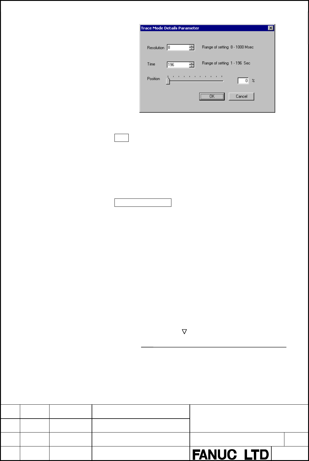
Fig. 9.10.5(b)
Time
This item is displayed when [Time Cycle] is selected for the
sampling mode. Set the sampling time. The valid data range of this
item varies depending on the setting of [Resolution] and the number
of signals to be sampled. The valid data range is displayed in the
dialog box.
Stop Trigger Position
This item is displayed when the tracing stop condition is
[TRIGGER]. Specify where the time at which the stop trigger
condition is satisfied is placed during the entire sampling time (or
count) with the ratio of the time to the sampling time (or count).
Set the ratio according to the purpose. For example, to check the
signal changes before the trigger condition is satisfied, set a large
value; to check the signal changes after the trigger condition is
satisfied, set a small value.
Example
Graph display range when the sampling time is 10 sec and the
sampling position is 10%:
Trigger position
<-1 sec-> <---- 9 sec ---->
| | |
-1 0 9 (SEC)
Contents Summary of FAPT Ladder-III Operators manual
- Page 1FANUC LADDER-III OPERATOR’S MANUAL B-66234EN/05
- Page 2• No part of this manual may be reproduced in any form. • All specifications and designs are subject to change without notice. The export of this product is subject to the authorization of the government of the country from where the product is exported. In this manual we have tried as much as possi
- Page 3B-66234EN/05 SAFETY PRECAUTIONS SAFETY PRECAUTIONS This manual includes safety precautions for protecting the user and preventing damage to the machine. Precautions are classified into Warnings and Cautions according to their bearing on safety. Also, supplementary information is described as Notes.
- Page 4SAFETY PRECAUTIONS B-66234EN/05 1.1 GENERAL WARNINGS AND CAUTIONS The following warnings and note describe precautions on handling CNCs, which must be observed to ensure safety when using machines equipped with a CNC. WARNING 1 Before operating the machine, thoroughly check the entered data. Operati
- Page 5B-66234EN/05 SAFETY PRECAUTIONS 1.2 WARNINGS AND NOTES RELATING TO FANUC LADDER-III Warnings and notes relating to FANUC LADDER-III appear in this manual. Before using the software, read this manual thoroughly and take time to read the Warnings, Cautions, and Notes in this manual carefully. In addit
- Page 6SAFETY PRECAUTIONS B-66234EN/05 1.3 READ THE FOLLOWING: The following summarizes the points that the user should keep in mind when using FANUC LADDER-III. Before using FANUC LADDER-III, read the following: CAUTION In this manual we have tried as much as possible to describe all the various matters.
- Page 7B-66234EN/05 PREFACE PREFACE Renaming This software has been renamed as follows: Old name: FAPT LADDER-III New name: FANUC LADDER-III Any specifications of this software have not been changed (they are same as of the product with the old name). If the old name is displayed by any FANUC PMC programmi
- Page 8PREFACE B-66234EN/05 NOTE This software you purchased can be used on a single computer. When using this software on more than one computer, you must be licensed to use as many copies of this software as the number of the computers being used, even if you are not running this software on multiple com
- Page 9B-66234EN/05 PREFACE 1.1 FEATURES OF FANUC LADDER-III This software has the following features: Features This software provides a Windows-based environment for developing sequence programs for FANUC PMCs, therefore providing the user with easy-to-use operating environment. CNC/PMC Machine RS-232C, E
- Page 10PREFACE B-66234EN/05 • Main functions ⋅ Inputting, displaying, editing, and outputting sequence programs - Monitoring and debugging sequence programs (Displaying the signal status, alarms, and PMC status, and ladder diagram online monitoring) - Setting and displaying PMC parameters - Executing and s
- Page 11B-66234EN/05 PREFACE NOTE *1 • Available when the PMC software series and edition are 4066/12, 4068/11, or later and the CNC software series and edition are B0A1/23, B1A1/20, BDA1/12, BEA1/12, or later. *2 • Available when the PMC software series and edition are 4074/01 or later. Not available with
- Page 12PREFACE B-66234EN/05 1.3 ORGANIZATION OF THIS MANUAL This manual is organized as follows: SAFETY PRECAUTIONS Describes general precautions that must be observed to ensure the safe use of this software. PREFACE Briefly describes the main features of this software. Also describes how to use this manua
- Page 13B-66234EN/05 PREFACE 1.4 NOTATION CONVENTIONS IN THIS MANUAL This manual uses the following notation and conventions: • Menus, commands, and screens Notation example Explanation [File] menu Menu names appear in brackets ([ ]). [Setting…] Command names appear in brackets ([ ]). [Program List] screen
- Page 14PREFACE B-66234EN/05 • PMC models In this manual, the PMC models are abbreviated as follows: PMC Model Abbreviations Abbreviation PMC model 30i-A PMC PMC for Series 30i-A (1st-path PMC) 30i-A PMC(2nd) PMC for Series 30i-A (2nd-path PMC) 30i-A PMC(3rd) PMC for Series 30i-A (3rd-path PMC) 30i-A PMC(DC
- Page 15B-66234EN/05 TABLE OF CONTENTS TABLE OF CONTENTS SAFETY PRECAUTIONS............................................................................s-1 PREFACE ....................................................................................................p-1 1 SETUP..................................
- Page 16TABLE OF CONTENTS B-66234EN/05 3.4 EDITING TITLES ......................................................................................... 36 3.4.1 Procedure................................................................................................................36 3.5 EDITING LADDER DIAGRAMS
- Page 17B-66234EN/05 TABLE OF CONTENTS 3.5.24.6 Entering and deleting vertical lines ................................................................. 105 3.5.25 Deleting Symbol or Comment Data .....................................................................106 3.5.26 Undo / Redo ......................
- Page 18TABLE OF CONTENTS B-66234EN/05 3.9 EDITING I/O MODULE ASSIGNMENT ..................................................... 152 3.9.1 Procedure..............................................................................................................152 3.9.2 Tool bar .................................
- Page 19B-66234EN/05 TABLE OF CONTENTS 4.7.1 Procedure..............................................................................................................202 4.8 PRINTING CROSS-REFERENCES .......................................................... 204 4.8.1 Procedure................................
- Page 20TABLE OF CONTENTS B-66234EN/05 6.7 FORMAT OF EXTERNAL SYMBOL FILE ................................................. 269 6.7.1 Option...................................................................................................................270 6.7.2 Sample of an External Symbol File..........
- Page 21B-66234EN/05 TABLE OF CONTENTS 9.1.1 Procedure..............................................................................................................305 9.1.2 [Monitor] Screen ..................................................................................................306 9.1.3 [Edit] Sc
- Page 22TABLE OF CONTENTS B-66234EN/05 9.3.6.1 Programmer protect function ........................................................................... 328 9.3.6.2 Procedure ......................................................................................................... 329 9.3.6.3 Setting items ...
- Page 23B-66234EN/05 TABLE OF CONTENTS 9.10.5 Setting Details of Trace Mode..............................................................................357 9.10.6 Setting Trace Parameters (Sampling Addresses)..................................................358 9.10.7 Context Menu .........................
- Page 24TABLE OF CONTENTS B-66234EN/05 11.2.7 Search ...................................................................................................................393 11.3 EDITING LADDER DIAGRAMS................................................................. 395 11.3.1 How to View whole Program .....
- Page 25B-66234EN/05 TABLE OF CONTENTS 11.14.1 Toolbar .................................................................................................................426 11.15 D ADDRESS (DATA TABLE)..................................................................... 426 11.15.1 Toolbar ..................
- Page 26TABLE OF CONTENTS B-66234EN/05 13.2.11 Input/Output .........................................................................................................465 13.2.12 Online ...................................................................................................................466 APPEN
- Page 27B-66234EN/05 1.SETUP 1 SETUP This chapter describes the operating environment of FANUC LADDER-III. This chapter also describes how to set up FANUC LADDER-III to make software ready for use. -1-�
- Page 281.SETUP B-66234EN/05 1.1 OPERATING ENVIRONMENT The operating environment required for this software is as follows: • Computer PC/AT-compatible computer running Windows 98 SE, NT4.0, 2000, Me, or XP (English/Japanese system) • CPU Pentium 133 MHz or better • Memory For Windows 98 SE ⋅ 16MB or more (3
- Page 29B-66234EN/05 1.SETUP 1.2 INSTALLATION AND UNINSTALLATION This section describes how to install or uninstall this software. NOTE 1 Both of FAPT LADDER-III and FANUC LADDER-III cannot be installed on the same personal computer. 2 Normally, when FANUC LADDER-III is installed, FAPT LADDER-III is automat
- Page 301.SETUP B-66234EN/05 3 Starting setup and confirming the license agreement 3-1 FANUC LADDER-III setup starts, displaying the [Choose Setup Language] screen. Select Japanese or English, and then click the
button. Fig. 1.2.1 (a) 3-2 The [Welcome to the InstallShield Wizard for FANUC LADDER-III] s - Page 31B-66234EN/05 1.SETUP 3-3 Click the
button. Then, the [License Agreement] screen appears. Fig. 1.2.1 (c) 3-4 When you agree to the terms of the license agreement, and wish to continue installation, click the button. Clicking the button stops installation. -5-� - Page 321.SETUP B-66234EN/05 4 Entering user information 4-1 The [Customer Information] screen appears. Fig. 1.2.1 (d) 4-2 Enter [User Name], [Company Name], and [Serial Number] and then click the
button. Then, the [Registration Confirmation] screen appears. Fig. 1.2.1 (e) 4-3 Check that the registra - Page 33B-66234EN/05 1.SETUP 5 Selecting the installation destination and program folder 5-1 The [Choose Destination Location] screen appears. Fig. 1.2.1 (f) 5-2 By default, the program is installed in C:\Program Files\FANUC PMC Programmer\FANUC LADDER-3. To change the installation destination, click the [B
- Page 341.SETUP B-66234EN/05 6 Starting file copy operation and ending the installation 6-1 The [Start Copying Files] screen appears. Fig. 1.2.1 (h) 6-2 Information for starting the program file copy operation is displayed. To change the information, click the
button. Check that the displayed informa - Page 35B-66234EN/05 1.SETUP 1.2.2 Uninstallation Procedure 1 Terminating FANUC LADDER-III 1-1 FANUC LADDER-III cannot be uninstalled while it is running. Terminate FANUC LADDER-III, and then uninstall it. 2 Starting the uninstaller 2-1 Click [Start Menu] - [Settings] - [Control Panel]. 2-2 On the [Control
- Page 361.SETUP B-66234EN/05 3 Confirming uninstallation 3-1 A dialog box appears, asking whether you really want to uninstall the program. Select
. Fig. 1.2.2 (b) 4 Executing uninstallation The installed files, folders, and start menu items are deleted, and the original system settings are restored. Un - Page 37B-66234EN/05 2.BASICS 2 BASICS This chapter describes the basic items the user should understand before using FANUC LADDER-III. - 11 -�
- Page 382.BASICS B-66234EN/05 2.1 START AND END This section describes how to start and end FANUC LADDER-III. 2.1.1 Starting FANUC LADDER-III To start this software, use the following procedure: Procedure 1 Click the [Start] button. 2 From the [Start] menu, select [Program]. 3 From the [Program] menu, selec
- Page 39B-66234EN/05 2.BASICS 2.2 WINDOW NAMES AND FUNCTIONS This section describes the names and functions of the windows displayed by this software. As shown in the figure below, child windows are displayed within the parent window. These are required for operations such as the creation of sequence progra
- Page 402.BASICS B-66234EN/05 2.2.1 Main Menu Each main menu has submenus, as listed below. Table 2.2.1 Main menu Submenu Reference chapter, section, or subsection File New Program 3.2 CREATING NEW PROGRAMS Open Program 3.3 OPENING EXISTING PROGRAMS Close Program 3.13 CLOSING PROGRAMS Save 3.11 SAVING PROGR
- Page 41B-66234EN/05 2.BASICS Table 2.2.1 Main menu Submenu Reference chapter, section, or subsection Tool Mnemonic Convert 6.1 CONVERTING SOURCE PROGRAMS TO MNEMONIC FILES Source Program Convert 6.2 CONVERTING MNEMONIC FILES TO SOURCE PROGRAMS Data Conversion 12 CONVERTING SEQUENCE PROGRAMS Data File→LAD F
- Page 422.BASICS B-66234EN/05 2.2.2 Toolbar The toolbar contains a set of buttons used for file operations and editing. <1> <2> <3> <4> <5> <6> <7> <8> <9><10><11><12><13><14> Fig. 2.2.2 <1> New Program Creates a new program. <2> Open Program Opens an existing program <3> Save Saves a program. <4> Cut Remov
- Page 43B-66234EN/05 2.BASICS 2.2.3 Edit Toolbar The edit tool bar contains a set of buttons used for editing ladder diagrams. You can input contacts and coils by using the edit tool bar. See Section 3.5, "EDITING LADDER DIAGRAMS" for details. 2.2.4 Soft Keys To perform operations with the currently selecte
- Page 442.BASICS B-66234EN/05 2.3 DISPLAYING VERSION INFORMATION This section describes how to display the version information of this software for purposes of, for example, maintenance. Procedure Select [Help] - [About version information…]. Fig. 2.3 - 18 -
- Page 45B-66234EN/05 3.CREATING AND EDITING SEQUENCE PROGRAMS 3 CREATING AND EDITING SEQUENCE PROGRAMS This chapter describes how to create and edit sequence programs. A sequence program consists of a title, system parameters, symbols, comments, I/O modules, messages, and ladder/step sequences. - 19 -�
- Page 463.CREATING AND EDITING SEQUENCE PROGRAMS B-66234EN/05 3.1 SEQUENCE PROGRAMS This section describes sequence programs. 3.1.1 Procedure for Creating Sequence Programs The following flowchart illustrates the procedure for creating a sequence program. Start control system development Determine targets o
- Page 47B-66234EN/05 3.CREATING AND EDITING SEQUENCE PROGRAMS • Sequence programs A sequence program consists of the data listed below. - Title data - System parameters - Symbols/comments - Message data - I/O module data - I/O module comments - Ladder level 1 - Ladder level 2 - Ladder level 3 - Ladder subpr
- Page 483.CREATING AND EDITING SEQUENCE PROGRAMS B-66234EN/05 In FANUC LADDER-III, a file with extension .LAD (hereafter called a LAD file) holds all sequence program data. Sequence program (LAD file) Source program System parameters Title data Symbols/comments Message data I/O module data I/O module commen
- Page 49B-66234EN/05 3.CREATING AND EDITING SEQUENCE PROGRAMS • Data flow FANUC LADDER-III Source program Mnemonic conversion Mnemonic program System parameters Conventional mnemonic not Title data Source conversion using step sequences Symbols/comments Message data I/O module data I/O module comments Ladde
- Page 503.CREATING AND EDITING SEQUENCE PROGRAMS B-66234EN/05 3.1.2 PMC Programming Method The ladder method is one of the most extensively used methods for programming PMC-based sequence control. Because this method was originally based on control circuits in relay panels, it was initially easy for sequenc
- Page 51B-66234EN/05 3.CREATING AND EDITING SEQUENCE PROGRAMS 3.1.3 Work Folders and Online Program Files • Work folder A program work folder is created automatically on a path set up in the TMP environment variable. The work folder is called WFLAD* where * represents any number. • User file folder A user f
- Page 523.CREATING AND EDITING SEQUENCE PROGRAMS B-66234EN/05 3.1.4 Device Selection Selection of CNC Main and LOADER When the Loader control board is attached and both the Main side and the Loader side PMC can communicate, the following dialog is displayed. Please specify the connected controller. When cur
- Page 53B-66234EN/05 3.CREATING AND EDITING SEQUENCE PROGRAMS Selection of Multi-path PMC [Selection of device] dialog box appears by the following operation. • Starting the communication to PMC when no program is opened. • Starting the communication to PMC when PMC type of the opened program does not suppo
- Page 543.CREATING AND EDITING SEQUENCE PROGRAMS B-66234EN/05 3.2 CREATING NEW PROGRAMS This section describes how to create a sequence program (LAD file). 3.2.1 Procedure 1 Select [File] - [New Program]. The [New Program] screen appears. Fig. 3.2.1(a) Fig. 3.2.1(b) - 28 -�
- Page 55B-66234EN/05 3.CREATING AND EDITING SEQUENCE PROGRAMS 1-1 Set the necessary data. Name Enter the name of a program file you want to create. Use the extension .LAD. You can omit it, however. PMC Type Select a PMC model. LEVEL3 Program Using Select this item if you want to enable ladder level 3. I/O L
- Page 563.CREATING AND EDITING SEQUENCE PROGRAMS B-66234EN/05 2 To create a program, click the
button. The [Program List] screen appears. To quit, click the button. NOTE A new ladder program is created in the last file folder used for creating or modifying a ladder program. - 30 -� - Page 57B-66234EN/05 3.CREATING AND EDITING SEQUENCE PROGRAMS 3.3 OPENING EXISTING PROGRAMS This section describes how to open an existing sequence program (LAD file). 3.3.1 Procedure 1 Select [File] - [Open Program]. The [Open] screen appears. Fig. 3.3.1 1-1 Set the necessary data. File name Enter the name
- Page 583.CREATING AND EDITING SEQUENCE PROGRAMS B-66234EN/05 3.3.2 Opening Programs Opened by Another User This subsection describes access by multiple users to the same file on the network. 1 If a user attempts to open a program that is already opened by another user, the [File is opened...] screen appear
- Page 59B-66234EN/05 3.CREATING AND EDITING SEQUENCE PROGRAMS
button This button is the same as described in Item 1 above. button This button opens a file with a privilege. If this button is selected, the first user cannot overwrite the file, but can save the file only by assigning a new - Page 603.CREATING AND EDITING SEQUENCE PROGRAMS B-66234EN/05 3.3.3 Opening Programs with the Read-only Attribute When a program with the read-only attribute is opened, a character string (for read-only indication) is added after the file name in the status bar. Such a file cannot be overwritten, but can be
- Page 61B-66234EN/05 3.CREATING AND EDITING SEQUENCE PROGRAMS 5 The [New Program] dialog appears. And select appropriate PMC type from the list in the “New Program” dialog, where PMC types that matches with the importing memory card format file are listed. Fig. 3.3.4(c) Click
button, then importing is - Page 623.CREATING AND EDITING SEQUENCE PROGRAMS B-66234EN/05 3.4 EDITING TITLES This section describes how to enter a title for a program created by the machine tool builder. NOTE Titles can be displayed and edited only when the current programmer mode (offline/online) is offline. To change the programmer
- Page 63B-66234EN/05 3.CREATING AND EDITING SEQUENCE PROGRAMS 1-1 Set the necessary data. The maximum number of characters that can be entered is as listed below: Table 3.4.1 Maximum number of Data characters that can be entered Machine Tool Builder Name 32 Machine Tool Name 32 PMC & NC Name 32 PMC Program
- Page 643.CREATING AND EDITING SEQUENCE PROGRAMS B-66234EN/05 3.5 EDITING LADDER DIAGRAMS This section describes how to edit ladder diagrams. Two different methods can be used to edit ladder diagrams. The first method is offline editing, in which a personal computer for editing ladder diagrams is used stand
- Page 65B-66234EN/05 3.CREATING AND EDITING SEQUENCE PROGRAMS 3.5.2 Preparing for Online Editing Starting online editing Procedure 1. Connect the personal computer to the CNC (PMC) with a data transfer cable. (See Appendix A for an explanation about the data transfer cable.) 2. Check the current programmer
- Page 663.CREATING AND EDITING SEQUENCE PROGRAMS B-66234EN/05 Terminating online editing Procedure 1. Select [Ladder] - [Online/Offline] or click the [On Line/Off Line Change] button to change the programmer mode to offline. If the ladder program in the PMC is not updated, the following dialog box appears.
- Page 67B-66234EN/05 3.CREATING AND EDITING SEQUENCE PROGRAMS Summary of the ladder diagram editing screen Resize button Address display format Update button Ladder program name Undo button Search button Zoom-out button Zoom-in button Display always button Display window Insert button Delete all button Repl
- Page 683.CREATING AND EDITING SEQUENCE PROGRAMS B-66234EN/05 Replace button Replaces ladders in the ladder program (display window) with those in the edit window. Erase all button Erases all ladders from the edit window. Update button(for online editing only) Updates the ladders in the PMC with the those i
- Page 69B-66234EN/05 3.CREATING AND EDITING SEQUENCE PROGRAMS Display always Ctrl+T Keeps the ladder diagram editing window displayed. When the ON, multiple Ladder windows can be displayed at the same time. When the OFF, if another ladder diagram editing window is opened, the displayed window is automatical
- Page 703.CREATING AND EDITING SEQUENCE PROGRAMS B-66234EN/05 Edit tool bar Fig. 3.5.3 (g) The edit tool bar contains buttons for entering relays and coils, using the mouse. When you click a button on the edit tool bar and move the mouse pointer to the edit window, the mouse pointer changes its shape to the
- Page 71B-66234EN/05 3.CREATING AND EDITING SEQUENCE PROGRAMS Table 3.5.3 Shortcut key Function [Ctrl] + [A] Edit – Select all [Ctrl] + [C] Edit – Copy [Ctrl] + [D] Edit – Address display switch [Ctrl] + [F] Edit – Search [Ctrl] + [G] Edit – Jump to specified net number [Ctrl] + [H] Edit – Replace [Ctrl] +
- Page 723.CREATING AND EDITING SEQUENCE PROGRAMS B-66234EN/05 3.5.4 Changing Ladder Programs This subsection describes how to modify ladder programs. NOTE 1 To modify a ladder program, copy ladders from the display window to the edit window. Then, change them on the display window and substitute the ladders
- Page 73B-66234EN/05 3.CREATING AND EDITING SEQUENCE PROGRAMS 2. Press the [Enter] key. (Alternatively, double-click the ladder you want to modify.) Fig. 3.5.4 (b) 3. Modify the ladder on the edit window. For an explanation of how to operate ladders on the edit window, see the subsections listed below: Tabl
- Page 743.CREATING AND EDITING SEQUENCE PROGRAMS B-66234EN/05 4. After you finished modifying ladders, click the
button. Fig. 3.5.4 (c) 5. Select the replacement position, using the [↓] key or [↑] key, and then click the button Fig. 3.5.4 (d) - 48 - - Page 75B-66234EN/05 3.CREATING AND EDITING SEQUENCE PROGRAMS 3.5.5 Inserting Ladders from the Edit Window into a Ladder Program This subsection describes how to insert ladders from the edit window into a ladder program (on the display window). NOTE 1 If there is a ladder error in a ladder in the edit windo
- Page 763.CREATING AND EDITING SEQUENCE PROGRAMS B-66234EN/05 2. Click the
button. Fig. 3.5.5 (b) 3. Select the insertion position, using the [↓] key or [↑] key, and then click the button. Fig. 3.5.5 (c) - 50 - - Page 77B-66234EN/05 3.CREATING AND EDITING SEQUENCE PROGRAMS 3.5.6 Entering Basic Instructions This subsection describes how to enter basic instructions (relays and coils) in the edit window. Procedure 1 Position the cursor to the point where you want to enter a basic instruction, using the cursor control
- Page 783.CREATING AND EDITING SEQUENCE PROGRAMS B-66234EN/05 3 Position the cursor to the basic instruction you entered, using the cursor control keys, and then press the [Enter] key. (Alternatively, double-click the basic instruction.) Fig. 3.5.6 (b) 4 Enter an address or symbol, and then press the [Enter
- Page 79B-66234EN/05 3.CREATING AND EDITING SEQUENCE PROGRAMS After entering an address or symbol, you can enter basic instructions using function keys. Procedure 1 Position the cursor to the point where you want to enter a basic instruction, using the cursor control keys. (Alternatively, click the point.)
- Page 803.CREATING AND EDITING SEQUENCE PROGRAMS B-66234EN/05 3 Press the key that corresponds to the basic instruction you want to enter. (See Table 3.5.6.) Fig. 3.5.6 (f) - 54 -�
- Page 81B-66234EN/05 3.CREATING AND EDITING SEQUENCE PROGRAMS 3.5.7 Entering Function Instructions This subsection describes how to enter function instructions in the edit window. Procedure 1 Position the cursor to the point where you want to enter a function instruction, using the cursor control keys. (Alt
- Page 823.CREATING AND EDITING SEQUENCE PROGRAMS B-66234EN/05 3 Select the function instruction you want to enter, and then press the
button. Fig. 3.5.7 (c) 4 Enter the parameters for the instruction you entered. Fig. 3.5.7 (d) - 56 -� - Page 83B-66234EN/05 3.CREATING AND EDITING SEQUENCE PROGRAMS After entering a function instruction number or name, you can enter a function instruction using the [F9] key. Procedure 1 Position the cursor to the point where you want to enter a function instruction, using the cursor control keys. (Alternativ
- Page 843.CREATING AND EDITING SEQUENCE PROGRAMS B-66234EN/05 3 Press the [F9] key. Fig. 3.5.7 (g) - 58 -�
- Page 85B-66234EN/05 3.CREATING AND EDITING SEQUENCE PROGRAMS 3.5.8 Entering Horizontal Lines This subsection describes how to enter horizontal lines in the edit window. Procedure 1. Position the cursor to the point where you want to enter a horizontal line. (Alternatively, click the point.) Fig. 3.5.8 (a)
- Page 863.CREATING AND EDITING SEQUENCE PROGRAMS B-66234EN/05 3.5.9 Entering and Deleting Vertical Lines This subsection describes how to enter and delete vertical lines in the edit window. Procedure 1. Position the cursor to the point where you want to enter a vertical line, using the cursor control keys.
- Page 87B-66234EN/05 3.CREATING AND EDITING SEQUENCE PROGRAMS 3.5.10 Adding Ladder Subprograms This subsection describes how to add ladder subprograms. Procedure 1. Right-click on the program list screen, and then click [Add sub-program F9]. Fig. 3.5.10 (a) 2. The [Add sub-program] dialog box appears. Fig.
- Page 883.CREATING AND EDITING SEQUENCE PROGRAMS B-66234EN/05 3.5.11 Deleting Ladder Subprograms This subsection describes how to delete subprograms. Procedure 1. On the program list screen, position the pointer to the subprogram you want to delete and right-click. Then, click [Delete sub-program F6]. Fig.
- Page 89B-66234EN/05 3.CREATING AND EDITING SEQUENCE PROGRAMS 3. Delete the symbols and relay comments from a subprogram. Fig. 3.5.11 (c) 3-1 Click the right mouse button and select [Property]. 3-2 Click the [Symbol&RelayComment Delete] button. - 63 -�
- Page 903.CREATING AND EDITING SEQUENCE PROGRAMS B-66234EN/05 3.5.12 Editing Net Comments This subsection describes how to edit net comments. Procedure for adding net comments Procedure 1. In the display window, position the mouse pointer to the point where you want to add a net comment, and then right-clic
- Page 91B-66234EN/05 3.CREATING AND EDITING SEQUENCE PROGRAMS 3. After you finish entering the net comment, press the
button. Fig. 3.5.12 (d) Procedure for editing net comments Procedure 1. In the display window, double-click the net comment you want to modify. The [Net comment] screen appears. Fig. 3. - Page 923.CREATING AND EDITING SEQUENCE PROGRAMS B-66234EN/05 3.5.13 Deleting Net Comments This subsection describes how to delete net comments. Procedure 1. In the display window, position the mouse pointer to the net comment you want to delete, and then right-click. Fig. 3.5.13 (a) 2. Select [Delete] - [N
- Page 93B-66234EN/05 3.CREATING AND EDITING SEQUENCE PROGRAMS 3.5.14 Adding Page Breaks This subsection describes how to add page breaks. Procedure 1. In the display window, position the mouse pointer to the point where you want to add a page break, and then right-click. Fig. 3.5.14 2. Select [Insert] - [Ne
- Page 943.CREATING AND EDITING SEQUENCE PROGRAMS B-66234EN/05 3.5.15 Deleting Page Breaks This subsection describes how to delete page breaks. Procedure 1. In the display window, position the mouse pointer to the page break you want to delete, and then right-click. Fig. 3.5.15 (a) 2. Select [Delete] - [New
- Page 95B-66234EN/05 3.CREATING AND EDITING SEQUENCE PROGRAMS 3.5.16 Deleting Nets This subsection describes how to delete nets. Procedure 1. In the display window, select the range of nets you want to delete, using the mouse or cursor control keys. 2. Position the mouse pointer to the selected range, and t
- Page 963.CREATING AND EDITING SEQUENCE PROGRAMS B-66234EN/05 3.5.17 Search This subsection describes the ladder program search function. Procedure 1. Choose [Search] from the [Edit] menu. The [Search] screen appears. Fig. 3.5.17(a) 1-1 Search kind Select Address/Symbol or Functional instruction. 1-2 Progra
- Page 97B-66234EN/05 3.CREATING AND EDITING SEQUENCE PROGRAMS 2. When Address/Symbol is selected Fig. 3.5.17(c) 2-1 Instruction for search Check search target instructions. All Searches for all types of instructions. Select Select a desired instruction you want to search for. Write coils Searches for only w
- Page 983.CREATING AND EDITING SEQUENCE PROGRAMS B-66234EN/05 4. Specify a character string you want to search for. 4-1 Search string Enter a character string to be searched for. In a character string to be found, two types of wildcards can be used: a question mark (?) and an asterisk (*). A wildcard substi
- Page 99B-66234EN/05 3.CREATING AND EDITING SEQUENCE PROGRAMS 3.5.17.1 Context menu Search is possible with the easy operation by right-click operation of the mouse. The context menu is displayed by the right-click after you move cursor to the address or the functional instruction to search. You can search
- Page 1003.CREATING AND EDITING SEQUENCE PROGRAMS B-66234EN/05 3.5.17.2 Soft key The address, the symbol and the functional instruction in ladder diagram can be searched by the soft key. Two modes of operation can be chosen by the following check of the option screen: From the [Tool] menu, choose [Options],
- Page 101B-66234EN/05 3.CREATING AND EDITING SEQUENCE PROGRAMS 3.5.18 Collective Display Collective display is a function with which nets extracted under multiple search conditions can be monitored (in the online mode) and displayed in one window. 3.5.18.1 Setting collective display extraction conditions Pro
- Page 1023.CREATING AND EDITING SEQUENCE PROGRAMS B-66234EN/05 2. Click the
button. The [Search] screen appears. Fig. 3.5.18.1(c) 2-1 After setting search conditions, click the button. For each setting item, see Subsection 3.5.13, "Search." 3. The [Setting of search condition-name] scree - Page 103B-66234EN/05 3.CREATING AND EDITING SEQUENCE PROGRAMS 4. The [Collective Display] screen updated appears. Fig. 3.5.18.1(e) 5. Repeat steps 2 through 4 to add search conditions. Fig. 3.5.18.1(f) 5-1
button This button is used to edit the search condition where the cursor is placed. 5 - Page 1043.CREATING AND EDITING SEQUENCE PROGRAMS B-66234EN/05 6. Check the check boxes of search conditions to be enabled, then set a desired collective display condition name in Condition Name. Fig. 3.5.18.1(g) 6-1 Click the
button. Extracted nets are collectively displayed on the screen. The same inf - Page 105B-66234EN/05 3.CREATING AND EDITING SEQUENCE PROGRAMS 3.5.18.2 Executing collective display Procedure 1 On the [Program List] screen, move the mouse pointer to the extraction condition used for collective display execution, then click the right mouse button. Fig. 3.5.18.2(a) 2 Choose [Open]. Then, t
- Page 1063.CREATING AND EDITING SEQUENCE PROGRAMS B-66234EN/05 3.5.18.3 Modifying collective display extraction conditions Procedure 1. On the [Program List] screen, move the mouse pointer to an extraction condition to be modified, then click the right mouse button. Fig. 3.5.18.3 2. Choose [propeRty]. Then,
- Page 107B-66234EN/05 3.CREATING AND EDITING SEQUENCE PROGRAMS 3.5.18.4 Deleting collective display extraction conditions Procedure 1. On the [Program List] screen, move the mouse pointer to an extraction condition to be deleted, then click the right mouse button. Fig. 3.5.18.4(a) 2. Choose [Delete]. Then, a
- Page 1083.CREATING AND EDITING SEQUENCE PROGRAMS B-66234EN/05 3.5.19 Setting Ladder Display You can do the setting relevant to display and operation of the ladder diagram. • The number of contacts and coil per row can be specified. • The address, symbol, and comment of the basic instruction pointed with the
- Page 109B-66234EN/05 3.CREATING AND EDITING SEQUENCE PROGRAMS Fig. 3.5.19(b) The comment is 2 sets. Fig. 3.5.19(c) The comment is 4 sets. 1-1 Number of contacts + coil a line Set the desired number of contacts and coils per row. (A value from 8 to 20 (columns) can be set.) - 83 -�
- Page 1103.CREATING AND EDITING SEQUENCE PROGRAMS B-66234EN/05 NOTE 1 If the number of contacts and coils per row is changed, a ladder diagram in the edit window and clipboard is deleted, and reediting is disabled. 2 A net that has more relays or coils than the set number of contacts and coils is displayed a
- Page 111B-66234EN/05 3.CREATING AND EDITING SEQUENCE PROGRAMS 2. Click the
button. A dialog box appears. In this dialog box, specify the character font, colors, and connection line thickness displayed in a ladder diagram. Fig. 3.5.19(d) 2-1 Font Click the button. A dialog box appea - Page 1123.CREATING AND EDITING SEQUENCE PROGRAMS B-66234EN/05 2-2 Colors Click the
button. A dialog appears. In this dialog box, specify the colors of items displayed in a ladder diagram. Fig. 3.5.19(f) 2-3 Signal Off/Step Sequence Specifies the thickness of connection lines in the signal off s - Page 113B-66234EN/05 3.CREATING AND EDITING SEQUENCE PROGRAMS 3.5.20 Changing Signal Addresses and Function Instruction Parameters in the Display Window This subsection describes how to change signals addresses and function instruction parameters in the display window. Procedure 1. Position the cursor to th
- Page 1143.CREATING AND EDITING SEQUENCE PROGRAMS B-66234EN/05 3.5.21 Changing Contacts and Coils in the Display Window This subsection describes how to change contacts and coils in the display window. Procedure 1. Position the cursor to the contact or coil you want to change. Fig. 3.5.21 (a) 2. Click the so
- Page 115B-66234EN/05 3.CREATING AND EDITING SEQUENCE PROGRAMS 3.5.22 Checking the Number of Program Steps This subsection describes how to check the total number of steps in a ladder program and the number of steps in each subprogram. Procedure 1. On the [Program List] screen, position the pointer to a prog
- Page 1163.CREATING AND EDITING SEQUENCE PROGRAMS B-66234EN/05 1-2 LEVEL1 Displays the number of steps in each of LEVEL1 to LEVEL3. Fig. 3.5.22 (c) 1-3 Sub-program Displays the number of steps in each subprogram. Fig. 3.5.22 (d) NOTE 1 If a step sequence program is contained, the total number of program step
- Page 117B-66234EN/05 3.CREATING AND EDITING SEQUENCE PROGRAMS 3.5.23 Replace This subsection describes the ladder program replace function. Procedure 1. From the [Edit] menu, choose [Replace]. The [Replace] screen appears. Fig. 3.5.23 (a) 1-1 Program Click the
- Page 1183.CREATING AND EDITING SEQUENCE PROGRAMS B-66234EN/05 1-3 Replace string Enter a character string you want to replace with. In a character string to be replaced with, two types of wildcards can be used: a question mark (?) and an asterisk (*). NOTE 1 A wildcard can substitute for one or multiple cha
- Page 119B-66234EN/05 3.CREATING AND EDITING SEQUENCE PROGRAMS 3. Wild card 3-1 Asterisk (*) The following types of wildcard replacement using asterisks are available: Character string to be replaced with Y200 Y* Y200.1 Y*.1 Y200.* X100 A B B B B Character X* A B B B B string to be X100.0 B B A B B X*.0 B B
- Page 1203.CREATING AND EDITING SEQUENCE PROGRAMS B-66234EN/05 3.5.24 Changing Ladder Programs on the Display Window This subsection describes how to modify a ladder program only on the display window without using the edit window. 3.5.24.1 Changing the ladder editing mode From the [Tool] menu, choose [Optio
- Page 121B-66234EN/05 3.CREATING AND EDITING SEQUENCE PROGRAMS 3.5.24.2 Inserting an edit line Procedure Move the cursor to a position where you want to enter an edit line, using direction keys. Click the right mouse button and select the [Insert] menu. Fig. 3.5.24.2 - 95 -�
- Page 1223.CREATING AND EDITING SEQUENCE PROGRAMS B-66234EN/05 3.5.24.3 Entering basic instructions 1. This subsection describes how to enter basic instructions (relays and coils). Procedure 1-1 Position the cursor to the point where you want to enter a basic instruction, using the cursor control keys. (Alte
- Page 123B-66234EN/05 3.CREATING AND EDITING SEQUENCE PROGRAMS 1-3 Position the cursor to the basic instruction you entered, using the cursor control keys, and then press the [Enter] key. (Alternatively, double-click the basic instruction.) Fig. 3.5.24.3(b) 1-4 Enter an address or symbol, and then press the
- Page 1243.CREATING AND EDITING SEQUENCE PROGRAMS B-66234EN/05 2. After entering an address or symbol, you can enter basic instructions using function keys. Procedure 2-1 Position the cursor to the point where you want to enter a basic instruction, using the cursor control keys. (Alternatively, click the poi
- Page 125B-66234EN/05 3.CREATING AND EDITING SEQUENCE PROGRAMS 2-3 Press the key that corresponds to the basic instruction you want to enter. (See Table 3.5.24.3.) Fig. 3.5.24.3(f) - 99 -�
- Page 1263.CREATING AND EDITING SEQUENCE PROGRAMS B-66234EN/05 3.5.24.4 Entering function instructions 1. This subsection describes how to enter function. Procedure 1-1 Position the cursor to the point where you want to enter a function instruction, using the cursor control keys. (Alternatively, click the po
- Page 127B-66234EN/05 3.CREATING AND EDITING SEQUENCE PROGRAMS 1-3 Select the function instruction you want to enter, and then press the
button. Fig. 3.5.24.4(c) 1-4 Enter the parameters for the instruction you entered. Fig. 3.5.24.4(d) - 101 -� - Page 1283.CREATING AND EDITING SEQUENCE PROGRAMS B-66234EN/05 2 After entering a function instruction number or name, you can enter a function instruction using the [F9] key. Procedure 2-1 Position the cursor to the point where you want to enter a function instruction, using the cursor control keys. (Altern
- Page 129B-66234EN/05 3.CREATING AND EDITING SEQUENCE PROGRAMS 2-3 Press the [F9] key. Fig. 3.5.24.4(g) - 103 -�
- Page 1303.CREATING AND EDITING SEQUENCE PROGRAMS B-66234EN/05 3.5.24.5 Entering horizontal lines This subsection describes how to enter horizontal lines. Procedure 1. Position the cursor to the point where you want to enter a horizontal line. (Alternatively, click the point.) Fig. 3.5.24.5(a) 2. Press the [
- Page 131B-66234EN/05 3.CREATING AND EDITING SEQUENCE PROGRAMS 3.5.24.6 Entering and deleting vertical lines This subsection describes how to enter and delete vertical lines. Procedure 1. Position the cursor to the point where you want to enter a vertical line, using the cursor control keys. (Alternatively,
- Page 1323.CREATING AND EDITING SEQUENCE PROGRAMS B-66234EN/05 3.5.25 Deleting Symbol or Comment Data This subsection describes how to delete symbol or comment data in ladder diagram editing. Procedure 1. Move the cursor to the position of a basic instruction for which you want to delete symbol or comment da
- Page 133B-66234EN/05 3.CREATING AND EDITING SEQUENCE PROGRAMS 3.5.26 Undo / Redo This subsection describes the operation of Undo / Redo function on the ladder edit screen. Procedure 1. Select [Edit]-[Undo] from the menu-bar, or click the toolbar button, or push the shortcut key of [Ctrl]+[Z]. Then the previ
- Page 1343.CREATING AND EDITING SEQUENCE PROGRAMS B-66234EN/05 3.5.26.1 Setting the maximum number of undo operations. Procedure 1. Select [Tool]-[Option]. Then click the [Ladder] tab. 2. Move the cursor to [Undo max number], and set the maximum number of Undo operations. (Range of setting : 0 - 50) 3. Click
- Page 135B-66234EN/05 3.CREATING AND EDITING SEQUENCE PROGRAMS 3.5.27 Ladder Diagram is Outputted to the Text File The ladder diagram is outputted to the text file in the form currently displayed on the Ladder edit display. The outputted text file can be opened by text editors, such as "notepad", or it can b
- Page 1363.CREATING AND EDITING SEQUENCE PROGRAMS B-66234EN/05 2. [Output a text format file...] is selected from the [Tool] menu. Fig. 3.5.27.1 (b) 3. Input the output file name. Push the
button and the file is outputted. Fig. 3.5.27.1 (c) - 110 -� - Page 137B-66234EN/05 3.CREATING AND EDITING SEQUENCE PROGRAMS NOTE 1 The menu item can not be selected if there is an error net. 2 It is necessary to display and select the window of the ladder. 3 As to the storing folder of the text file, you can choose the default of the storing folder by the Specify the
- Page 1383.CREATING AND EDITING SEQUENCE PROGRAMS B-66234EN/05 3.5.27.2 The example of an output file Header information Ladder program Fig. 3.5.27.2(a) Header information Header information changes according to the kind of outputted program. Program Title All Ladder Diagram (ALL) LEVEL1 Ladder Diagram (LEVE
- Page 139B-66234EN/05 3.CREATING AND EDITING SEQUENCE PROGRAMS 3.5.27.3 Ladder diagram without the net number is output to the text file The setting to output the ladder diagram without the net number in the text file has been added. Since the net numbers are not output, you can compare the ladder diagrams b
- Page 1403.CREATING AND EDITING SEQUENCE PROGRAMS B-66234EN/05 3.5.28 Automatic Input of Timer, Counter, Rising / Falling-Edge Numbers This function automatically inputs the unused numbers for the parameters of functional instructions during ladder editing of offline mode and online mode. With this function,
- Page 141B-66234EN/05 3.CREATING AND EDITING SEQUENCE PROGRAMS CAUTION 1 Details are different between SUB3 (TMR) and SUB5 (CTR).For details, see "Automatic input of the TMR parameter of a functional instruction" and "Automatic input of the CTR parameter of a functional instruction", described later. 2 If yo
- Page 1423.CREATING AND EDITING SEQUENCE PROGRAMS B-66234EN/05 3.5.28.1 Automatic input of the TMR parameter of a functional instruction When inputting the TMR parameter, you must consider precision. Some contents of the display differ in offline editing and online editing. Offline editing (1) Range of param
- Page 143B-66234EN/05 3.CREATING AND EDITING SEQUENCE PROGRAMS 3.5.28.2 Automatic input of the CTR parameter of a functional instruction Online editing In online editing, the preset value and current value of an input counter number are displayed in the status line in the following format. Fig. 3.5.28.2(a) N
- Page 1443.CREATING AND EDITING SEQUENCE PROGRAMS B-66234EN/05 3.6 EDITING STEP SEQUENCES This section describes how to edit step sequence programs. NOTE Step sequence programs can be displayed and edited only when the current programmer mode (offline/online) is offline. To change the programmer mode to offl
- Page 145B-66234EN/05 3.CREATING AND EDITING SEQUENCE PROGRAMS Summary of step sequence program edit screen Address display method selection button Step sequence program name Search button Check button Zoom-in button Zoom-out button Cursor Information about element in cursor position Cursor position Fig. 3.6
- Page 1463.CREATING AND EDITING SEQUENCE PROGRAMS B-66234EN/05 Cursor position Displays the row and column of the current cursor position. NOTE The step sequence program edit screen consists of 32 horizontal elements by 64 vertical lines. Soft keys • When the Shift key is not pressed (the cursor is on the "p
- Page 147B-66234EN/05 3.CREATING AND EDITING SEQUENCE PROGRAMS Context menu Right-clicking the step sequence program edit screen displays this menu. Fig. 3.6 (g) Shortcut keys Table 3.6 Shortcut key Function [F3] Search (downward) [Shift] + [F3] Search (upward) Enter step program (step line) [F5] Enter trans
- Page 1483.CREATING AND EDITING SEQUENCE PROGRAMS B-66234EN/05 3.6.1 Step Sequence Configuration A step sequence program consists of the following elements: Step A step is a unit of processing in a program. • A step number [Sn] necessary to control execution and a subprogram [Pm] that describes actual proces
- Page 149B-66234EN/05 3.CREATING AND EDITING SEQUENCE PROGRAMS Initial step An initial step is a step that automatically becomes active when the program starts running. Except for this point, the initial step behaves in the same manner as ordinary steps. Control can be passed from a usual step to the initial
- Page 1503.CREATING AND EDITING SEQUENCE PROGRAMS B-66234EN/05 [Example of setting transition conditions] In this example, after an M7 code is decoded using the DEC function instruction, control is passed to the next step. Subprogram P1 Subprogram P101 NOTE The TRSET function instruction is intended to descr
- Page 151B-66234EN/05 3.CREATING AND EDITING SEQUENCE PROGRAMS Beginning of parallel branch A branch occurs from one step to two or more steps, which become active simultaneously. • A transition is placed above a branch. • After branching, all steps become active simultaneously and are executed. • A branch c
- Page 1523.CREATING AND EDITING SEQUENCE PROGRAMS B-66234EN/05 End of parallel branch Two or more flows that branched out gather into one flow. • How parallel flows gather again is explained below. If transition P120 is satisfied, the processing of steps S10 and S20 is terminated, and step S21 becomes active
- Page 153B-66234EN/05 3.CREATING AND EDITING SEQUENCE PROGRAMS Jump A jump is processed in conjunction with a transition to control the execution of steps. • A jump-to label [Ln] is specified. • The step at a jump destination becomes active. • The jump destination must be within the same program. • It is imp
- Page 1543.CREATING AND EDITING SEQUENCE PROGRAMS B-66234EN/05 Initial block step The initial block step is an initial step in a block. • A step number [Sn] necessary to control execution and a subprogram [Pm] that describes actual processing are defined for an initial block step. • The function and represen
- Page 155B-66234EN/05 3.CREATING AND EDITING SEQUENCE PROGRAMS 3.6.2 Entering Steps Procedure 1. Position the cursor to the point where you want to enter a step. 2. Press the [F5] key. 3. The [Action] dialog box appears. Enter the necessary items. (An idle step number is used automatically.) Fig. 3.6.2 4. Af
- Page 1563.CREATING AND EDITING SEQUENCE PROGRAMS B-66234EN/05 3.6.3 Entering Transitions Procedure 1. Position the cursor to the point where you want to enter a transition. 2. Press the [F5] key. 3. The [Action] dialog box appears. Enter the desired action. Fig. 3.6.3 4. After you finish entering the action
- Page 157B-66234EN/05 3.CREATING AND EDITING SEQUENCE PROGRAMS 3.6.4 Beginning of Selective Branch Procedure 1. Position the cursor to the point where you want to enter the beginning of a selective branch. 2. Press the [F6] key. 3.6.5 End of Selective Branch Procedure 1. Position the cursor to the point wher
- Page 1583.CREATING AND EDITING SEQUENCE PROGRAMS B-66234EN/05 3.6.6 Beginning of Parallel Branch Procedure 1. Position the cursor to the point (transition line) where you want to enter the beginning of parallel branch. 2. Press the [F7] key. P100 3.6.7 End of Parallel Branch Procedure 1. Position the cursor
- Page 159B-66234EN/05 3.CREATING AND EDITING SEQUENCE PROGRAMS 3.6.8 Specifying Jump-to Label Procedure 1. Position the cursor to the point (step line) where you want to enter a jump-to label (a label to which a jump is to be made). 2. Hold down the [Shift] key, and then press the [F6] key. ← S1 3. The [Acti
- Page 1603.CREATING AND EDITING SEQUENCE PROGRAMS B-66234EN/05 3.6.9 Specifying Label Jump Procedure 1. Position the cursor to the point (step line) where you want to enter a label jump. 2. Hold down the [Shift] key, and then press the [F5] key. ←L10 S1 P10 P10 → S2 P10 3. The [Action] dialog box appears. En
- Page 161B-66234EN/05 3.CREATING AND EDITING SEQUENCE PROGRAMS 3.6.10 Checking Syntax Procedure 1. Press the [F9] key. • If no error is found, the following dialog box appears. Fig. 3.6.10 (a) • If an error is found, the following dialog box appears. Fig. 3.6.10 (b) - 135 -
- Page 1623.CREATING AND EDITING SEQUENCE PROGRAMS B-66234EN/05 3.6.11 Adding Step Sequence Subprograms This subsection describes how to add step sequence subprograms. Procedure 1. Right-click the program list screen, and then click [Add sub-program F9]. Fig. 3.6.11 (a) 2. The [Add sub-program] dialog box app
- Page 163B-66234EN/05 3.CREATING AND EDITING SEQUENCE PROGRAMS 3.6.12 Deleting Step Sequence Subprograms This subsection describes how to delete step sequence subprograms. Procedure 1. Position the pointer to the step sequence subprogram that you want to delete from the program list screen, and then right-cl
- Page 1643.CREATING AND EDITING SEQUENCE PROGRAMS B-66234EN/05 3.6.13 Search This subsection describes the step sequence program search function. Procedure 1. Choose [Find] from the [Edit] menu. The [Find] screen appears. Fig. 3.6.13 1-1 Search type Select Step number, Label number, or Symbol/address. 1-2 Se
- Page 165B-66234EN/05 3.CREATING AND EDITING SEQUENCE PROGRAMS 3.7 EDITING SYMBOLS AND COMMENTS This section describes how to edit symbols and comments. NOTE Symbols and comments can be displayed and edited only when the current programmer mode (offline/online) is offline. To change the programmer mode to of
- Page 1663.CREATING AND EDITING SEQUENCE PROGRAMS B-66234EN/05 Table 3.7.1 (c) Net comment Usable characters ASCII characters, kana, kanji, half-size kana Number of usable steps 2 steps/net comment Maximum number of characters 64 bytes/line or 4095 bytes/net comment Maximum number of lines 100 lines/net comm
- Page 167B-66234EN/05 3.CREATING AND EDITING SEQUENCE PROGRAMS NOTE 1 The maximum number of characters or lines, whichever is reached first, functions as a limit. 2 Relay comments are used only on the Ladder Edit screen of the FANUC LADDER-III. They are not included in a memory-card-type file generated by th
- Page 1683.CREATING AND EDITING SEQUENCE PROGRAMS B-66234EN/05 • In case of the PMC model supported to multiple comments. (30i/31i/32i-A) Fig. 3.7.2(c) • In case of the PMC model supported to multiple comments. (30i/31i/32i-A Extened function) Fig. 3.7.2(d) NOTE When you check [Ignore too long strings of the
- Page 169B-66234EN/05 3.CREATING AND EDITING SEQUENCE PROGRAMS 2 Click the
button on the toolbar. < Add New Data> button The [New Data] screen appears. • PMC model which does not support the multiple comments Fig. 3.7.2 (e) • PMC model which supports the multiple comments Fig. 3.7.2 (f) 2-1 Se - Page 1703.CREATING AND EDITING SEQUENCE PROGRAMS B-66234EN/05 3 To close the [Symbol/COMMENT] screen, click the
button. button This operation has nothing to do with whether to save the data entered on the [New Data] screen for [SYMBOL/COMMENT]. See Section 3.11, "Saving Programs," for an exp - Page 171B-66234EN/05 3.CREATING AND EDITING SEQUENCE PROGRAMS 3.8 EDITING MESSAGES Using the DISPB (SUB 41) function instruction enables the display of any message on the CRT or LCD screen of the CNC. This section describes how to create messages. NOTE Messages can be displayed and edited only when the curr
- Page 1723.CREATING AND EDITING SEQUENCE PROGRAMS B-66234EN/05 NOTE In Japanese-language input mode, Numeric data can be input according to the setting in “%%%flset.cnf” file of the install folder. (See subsection 3.8.4, “New line character, Numeric data” for detailes.) 3. Code input mode 3-1 Clicking the
- Page 173B-66234EN/05 3.CREATING AND EDITING SEQUENCE PROGRAMS 5. To close the [Message Editing] screen, click the
button. button This operation has nothing to do with whether to save the data entered on the [Message Editing] screen. See Section 3.11, "Saving Programs," for explanations about - Page 1743.CREATING AND EDITING SEQUENCE PROGRAMS B-66234EN/05 3.8.4 New Line Character, Numeric Data The input method of New line character and Numeric data is decided according to the input mode and the content of MSG_EDIT_VAL (the setting in “%%%flset.cnf” file). • The setting of MSG_EDIT_VAL in “%%%flset
- Page 175B-66234EN/05 3.CREATING AND EDITING SEQUENCE PROGRAMS • Input method of Numeric data (a) Numeric data format [Ibid, ____ ] Memory address that the numerical data is stored The address must be of binary format. Set the “bid” data after character ”I“: b : Number of bytes (1, 2, or 4) i : Number of dig
- Page 1763.CREATING AND EDITING SEQUENCE PROGRAMS B-66234EN/05 3.8.5 Tool Bar <1> <2> <3> <4> <5> <6> <7> <8> <9> <10> <11> <12> Fig. 3.8.5 <1> Search button Searches for a character string. <2> Search direction button Specifies the direction (upward or downward) in which a search is to be made. <3> Find wha
- Page 177B-66234EN/05 3.CREATING AND EDITING SEQUENCE PROGRAMS 3.8.6 Status Bar <1> Fig. 3.8.6 <1> The status bar displays the number of bytes in a message on the current line (that line with a caret). 3.8.7 Shortcut keys Table 3.8.7 Shortcut key Corresponding function [F3] Search [Shift]+[F3] Search directi
- Page 1783.CREATING AND EDITING SEQUENCE PROGRAMS B-66234EN/05 3.9 EDITING I/O MODULE ASSIGNMENT This section describes how to set and delete an address for each module in an I/O unit. NOTE I/O module assignment can be displayed and edited only when the current programmer mode (offline/online) is offline. To
- Page 179B-66234EN/05 3.CREATING AND EDITING SEQUENCE PROGRAMS 1-1 Double-click the line that you want to edit. The [Module] screen appears. Fig. 3.9.1 (c) 1-2 Select a module name from those that can be specified. Set the following data. Group Base Slot Comment NOTE I/O Unit MODEL-B assignment is carried ou
- Page 1803.CREATING AND EDITING SEQUENCE PROGRAMS B-66234EN/05 To assert the data you entered, click the
button. button To ignore the data, click the button. The [Edit I/O Module] screen appears. 2 To close the [Edit I/O Module] screen, click the button. button This operati - Page 181B-66234EN/05 3.CREATING AND EDITING SEQUENCE PROGRAMS 3.10 EDITING SYSTEM PARAMETERS This section describes how to edit system parameters. NOTE System parameters can be displayed and edited only when the current programmer mode (offline/online) is offline. To change the programmer mode to offline, s
- Page 1823.CREATING AND EDITING SEQUENCE PROGRAMS B-66234EN/05 1-1 Set the necessary data. Counter Data Type Initial value: BINARY Set the format of the counter value to be used in the CTR function instruction as binary or BCD. Ladder Exec (Valid only with the PMC-SC3/SC4, PMC-QC, PMC-NB/NB2, and PMC-SB7) In
- Page 183B-66234EN/05 3.CREATING AND EDITING SEQUENCE PROGRAMS FS0 Operator Panel Initial value: No FS0 machine operator's panel (check off) Specify whether the FS0 machine operator's panel is available. If you select this item, specify the actual DI/DO address connected to the machine operator's panel, the
- Page 1843.CREATING AND EDITING SEQUENCE PROGRAMS B-66234EN/05 1-2 Set the comment set number for displayed language of CNC (For PMC model which supports the multiple comments) In [Language for Comment] dialog-box (
button on [Edit System Parameter] screen), please set the comment set n - Page 185B-66234EN/05 3.CREATING AND EDITING SEQUENCE PROGRAMS 2 To close the [Edit System Parameter] screen, click the
button. button This operation has nothing to do with whether to save the data entered on the [Edit System Parameter] screen. See Section 3.11 "Saving Programs," for an expla - Page 1863.CREATING AND EDITING SEQUENCE PROGRAMS B-66234EN/05 3.11 SAVING PROGRAMS This section describes how to save new data to a sequence program (LAD file). 3.11.1 Procedure 1 Select [File] - [Save]. If the program has been updated, the [Program Update] screen appears. Fig. 3.11.1 1-1 Select the type of
- Page 187B-66234EN/05 3.CREATING AND EDITING SEQUENCE PROGRAMS 3.11.2 About the Deletion of the Unused Net Comment As a result of operation such as "Deletion of Subprograms," net comment data that is no longer used in the source program remains in the LAD file, occupying wasted space. When the LAD file is sa
- Page 1883.CREATING AND EDITING SEQUENCE PROGRAMS B-66234EN/05 3.12 SAVING PROGRAMS WITH NAMES This section describes how to name and save a sequence program (LAD file). 3.12.1 Procedure 1 Select [File] - [Save As]. The [Save As] screen appears. Fig. 3.12.1 1-1 Enter the file name you want to use. 1-2 To sav
- Page 189B-66234EN/05 3.CREATING AND EDITING SEQUENCE PROGRAMS 3.13 CLOSING PROGRAMS This section describes how to close a sequence program (LAD file). 3.13.1 Procedure 1 Select [File] - [Close Program]. Fig. 3.13.1 2 The [Program Update] screen appears. 2-1 Select the types of data that you want to update.
- Page 1903.CREATING AND EDITING SEQUENCE PROGRAMS B-66234EN/05 3.14 IMPORTING PROGRAMS This section describes how to import (copy in overwrite mode) data files, ladder diagrams, and subprograms from a LAD program to another sequence program that is currently open. It also explains how to import (convert and
- Page 191B-66234EN/05 3.CREATING AND EDITING SEQUENCE PROGRAMS ROM Format File A ROM format file is imported. It is written over a memory card file (MCARD) for the currently open sequence program. Handy-file Format File A Handy file format file is imported. It is written over a memory card file (MCARD) for t
- Page 1923.CREATING AND EDITING SEQUENCE PROGRAMS B-66234EN/05 3 Click the
button. The [Import/Export -- Specify import file name] screen appears. Fig. 3.14.1 (b) 3-1 Specify the file you want to import. - 166 -� - Page 193B-66234EN/05 3.CREATING AND EDITING SEQUENCE PROGRAMS ♦ If the FANUC LADDER-III file (*.LAD) is selected as an import-from file in step 2, above 4 Click the
button. The [Import/Export --Select Data File, Ladder Diagram, Subprogram, and/or User File] screen appears. Fig. 3.14.1 (c) 4-1 Select - Page 1943.CREATING AND EDITING SEQUENCE PROGRAMS B-66234EN/05 ♦ If the memory format file, ROM format file, and/or Handy file format files are selected as the types of files you want to import in step 2, above 4 Click the
button. The message “Import completed” appears. Fig. 3.14.1 (e) Click the - Page 195B-66234EN/05 3.CREATING AND EDITING SEQUENCE PROGRAMS ♦ If the memory card format file is selected as the type of file you want to import in step 2 above and the PMC type of the specified memory card format file is not compatible with the import destination program, a message appears, which indicate
- Page 1963.CREATING AND EDITING SEQUENCE PROGRAMS B-66234EN/05 3.14.2 Import of the External Symbol File This function inputs the symbol/comment of external symbol file format. External symbol files are composed of identification code and the comma separated text file. You can read symbol information from th
- Page 197B-66234EN/05 3.CREATING AND EDITING SEQUENCE PROGRAMS 4. Check the following item if necessary. Initialize Checked(Default) : Checked(Default) : After clearing all symbol/ symbol comment data, the symbol comment comment of the external symbol file is data before read. import Not checked : Not checke
- Page 1983.CREATING AND EDITING SEQUENCE PROGRAMS B-66234EN/05 3.15 EXPORTING PROGRAMS This section describes how to export (copy in overwrite mode) data files, ladder diagrams, and subprograms from the currently open sequence program to another LAD program. It also explains how to export (convert and copy i
- Page 199B-66234EN/05 3.CREATING AND EDITING SEQUENCE PROGRAMS Handy-file Format File A memory card file (MCARD) is exported from the currently open sequence program to a file in Handy file format. User File A user file is exported from the user file folder (MyFladder) for the currently open sequence program
- Page 2003.CREATING AND EDITING SEQUENCE PROGRAMS B-66234EN/05 NOTE As to the storing folder of the text file, you can choose the default of the storing folder by the Specify the same folder as a LAD file for working directory in the [General] tab of the option.(select the [Tool] - [Option...]) Checked......
- Page 201B-66234EN/05 3.CREATING AND EDITING SEQUENCE PROGRAMS 3-3 Select the export file in the following dialog. Fig. 3.15.1 (c) NOTE In the export of User File, only user files can be selected. 4. Click the
button. • Memory-card / ROM Format / Handy-file Format Fig. 3.15.1 (d) NOTE If a file with - Page 2023.CREATING AND EDITING SEQUENCE PROGRAMS B-66234EN/05 • FANUC LADDER-III(*.LAD) Fig. 3.15.1 (e) To export, click the
button. To return to the [Import/Export -- Select Data File, Ladder Diagram, Subprogram, and/or User File] screen without continuing, click the button. • User File Fig. 3.1 - Page 203B-66234EN/05 3.CREATING AND EDITING SEQUENCE PROGRAMS Operation 1. Select [File]-[Export...]. Then, the [Export] dialog appears. Fig. 3.15.2(a) Export dialog 2. Select External Symbol File from the list, push the
button. 3. Enter the file name to export. Fig. 3.15.2(b) - 177 -� - Page 2043.CREATING AND EDITING SEQUENCE PROGRAMS B-66234EN/05 4. Check Performing automatic address assignment if needed. This item appears when the PMC model is the extended function. Check this item if you use the external symbol file at the non-extended function. Check : The address of the symbol is assi
- Page 205B-66234EN/05 3.CREATING AND EDITING SEQUENCE PROGRAMS 3.16 OPENING MOST RECENTLY USED PROGRAMS This section describes how to open the most recently used programs (up to four). Procedure 1. Display the [File] menu. Fig. 3.16 2. Up to four most recently used programs are displayed above [Exit]. 3. Sel
- Page 2063.CREATING AND EDITING SEQUENCE PROGRAMS B-66234EN/05 3.17 CHECKING DUPLICATE COIL This section describes how to check duplicate coil. NOTE 1 When the programmer mode is only off-line, duplicate coil check is done for the source program of the ladder. 2 Duplicate coil check is not done for the step
- Page 207B-66234EN/05 3.CREATING AND EDITING SEQUENCE PROGRAMS 2. Select the check address on [Duplicate Coil – Address Setting] dialog. Fig. 3.17.1 (a) All All the output addresses are checked. Address An arbitrary output address is checked. Specification by the bit address and specification in the range to
- Page 2083.CREATING AND EDITING SEQUENCE PROGRAMS B-66234EN/05 3 To start Duplicate Coil Check, click
button on [Duplicate Coil – Address Setting] dialog box. The following dialog is displayed while checking duplicate coil. (Please click button to abort duplicate coil check.) Fig. 3.17.1 (c) 4 - Page 209B-66234EN/05 3.CREATING AND EDITING SEQUENCE PROGRAMS Soft Keys Fig. 3.17.1 (e) F4 Setting… [Duplicate Coil – Address Setting] dialog box is displayed. F5 Properties… Address property dialog box of cursor line is displayed. Fig. 3.17.1 (f) F9 Update When the source program of the ladder is updated,
- Page 2103.CREATING AND EDITING SEQUENCE PROGRAMS B-66234EN/05 3.18 PMC TYPE CHANGED AND SAVE You can convert the PMC model easily by saving the opened program after changing the PMC type to the specified one. Procedure 1. Select [File]-[PMC Type changed and save]. The [PMC Type changed and save] dialog appe
- Page 211B-66234EN/05 3.CREATING AND EDITING SEQUENCE PROGRAMS Table 3.18(a) Item Explanation Add(Merging the The symbols of the source program and object code Symbol/Comment are merged only for a symbol and comment. If the has given priority to same symbol and comment exist, the definition of the Memory car
- Page 2123.CREATING AND EDITING SEQUENCE PROGRAMS B-66234EN/05 NOTE 1 When you change Ladder program into other PMC type, please decide an address first. The PMC type cannot be changed when the address is not decided. 2 In the following cases, a ladder is not converted. • The address out of range on the targ
- Page 213B-66234EN/05 4.PRINTING SEQUENCE PROGRAMS 4 PRINTING SEQUENCE PROGRAMS This chapter describes how to print a sequence program, which consists of a title, system parameters, symbols, comments, I/O modules, messages, ladders and step sequences. - 187 -�
- Page 2144.PRINTING SEQUENCE PROGRAMS B-66234EN/05 4.1 PRINTING TITLES This section describes how to print title data. 4.1.1 Procedure 1. Select [File] - [Print]. The [Print] screen appears. Fig. 4.1.1 (a) 1-1 Select Title Data from Print Data. - 188 -�
- Page 215B-66234EN/05 4.PRINTING SEQUENCE PROGRAMS 1-2 Click the
- Page 2164.PRINTING SEQUENCE PROGRAMS B-66234EN/05 4.2 PRINTING LADDER DIAGRAMS This section describes how to print ladder diagrams. 4.2.1 Procedure 1. Select [File] - [Print]. The [Print] screen appears. Fig. 4.2.1 (a) 1-1 Select Ladder Diagram from Print Data. 1-2 Click the
- Page 217B-66234EN/05 4.PRINTING SEQUENCE PROGRAMS 2. Set up the following print options on the Ladder Diagram tab. Page No. Specify a start page number for ladder diagram printing (the Initially value is 1). Title Specify a title for ladder diagram printing (the Initially value is "Ladder Diagram"). Sub Tit
- Page 2184.PRINTING SEQUENCE PROGRAMS B-66234EN/05 4. To specify ladder diagram printing in detail, click the
button. Fig. 4.2.1 (c) Step No. (Initially selected.) Net No. (Initially selected.) Hide Line No. (Initially not selected.) Line Specify line spacing for nets (the Initially value is- Page 219B-66234EN/05 4.PRINTING SEQUENCE PROGRAMS 4.3 PRINTING STEP SEQUENCES This section describes how to print step sequences. 4.3.1 Procedure 1. Select [File] - [Print]. The [Print] screen appears. Fig. 4.3.1 (a) 1-1 Select Step Sequence Diagram from Print Data. If the PMC model does not support step se
- Page 2204.PRINTING SEQUENCE PROGRAMS B-66234EN/05 2. Set up the following print options on the Step Sequence Diagram tab. Page No. Specify a start page number for step sequence printing (the Initially value is 1). Title Specify a title for step sequence printing (the Initially value is "Step Sequence Diagra
- Page 221B-66234EN/05 4.PRINTING SEQUENCE PROGRAMS 4.4 PRINTING SYMBOLS AND COMMENTS This section describes how to print symbols and comments. 4.4.1 Procedure 1. Select [File] - [Print]. The [Print] screen appears. Fig. 4.4.1 (a) 1-1 Select Symbol & Comment from Print Data. - 195 -�
- Page 2224.PRINTING SEQUENCE PROGRAMS B-66234EN/05 1-2 Click the
- Page 223B-66234EN/05 4.PRINTING SEQUENCE PROGRAMS 3. To preview symbol printing, click the
button. 4. To set up the print options, click the button. To cancel the setup of the print options, click the button. The [Print] screen appears again. 5. To print, click the button. To qu - Page 2244.PRINTING SEQUENCE PROGRAMS B-66234EN/05 4.5 PRINTING MESSAGES This section describes how to print messages. 4.5.1 Procedure 1. Select [File] - [Print]. The [Print] screen appears. Fig. 4.5.1 (a) 1-1 Select Message Data from Print Data. 1-2 Click the
- Page 225B-66234EN/05 4.PRINTING SEQUENCE PROGRAMS 2. Set up the following print options on the Message tab. Page No. Specify a start page number for message printing (the Initially value is 1). Title Specify a title for message printing (the Initially value is "Message"). Sub Title Specify a subtitle for me
- Page 2264.PRINTING SEQUENCE PROGRAMS B-66234EN/05 4.6 PRINTING I/O MODULE ASSIGNMENT This section describes how to print I/O module assignments. 4.6.1 Procedure 1. Select [File] - [Print]. The [Print] screen appears. Fig. 4.6.1 (a) 1-1 Select I/O Module Data from Print Data. 1-2 Click the
- Page 227B-66234EN/05 4.PRINTING SEQUENCE PROGRAMS 2. Set up the following print options on the I/O Module tab. Page No. Specify a start page number for I/O module printing (the Initially value is 1). Title Specify a title for I/O module printing (the Initially value is "I/O Module"). Sub Title Specify a sub
- Page 2284.PRINTING SEQUENCE PROGRAMS B-66234EN/05 4.7 PRINTING SYSTEM PARAMETERS This section describes how to print system parameters. 4.7.1 Procedure 1. Select [File] - [Print]. The [Print] screen appears. Fig. 4.7.1 (a) 1-1 Select System Parameter from Print Data. 1-2 Click the
- Page 229B-66234EN/05 4.PRINTING SEQUENCE PROGRAMS 2. Set up the following print options on the System Parameter tab. Page No. Specify a start page number for system parameter printing (the Initially value is 1). Title Specify a title for system parameter printing (the Initially value is "System Parameter").
- Page 2304.PRINTING SEQUENCE PROGRAMS B-66234EN/05 4.8 PRINTING CROSS-REFERENCES This section describes how to print cross-references. 4.8.1 Procedure 1. Select [File] - [Print]. The [Print] screen appears. Fig. 4.8.1 (a) 1-1 Select Cross Reference from Print Data. 1-2 Click the
- Page 231B-66234EN/05 4.PRINTING SEQUENCE PROGRAMS 2. Set up the following print options on the Cross Reference tab. Page No. Specify a start page number for cross-reference printing (the Initially value is 1). Title Specify a title for cross-reference printing (the Initially value is "Cross Reference"). Sub
- Page 2324.PRINTING SEQUENCE PROGRAMS B-66234EN/05 Page Feed (Initially selected.) Line Feed Count Specify the number (0 to 9) of blank lines to be placed between addresses (the Initially value is 1). 3. To preview cross-reference printing, click the
button. 4. To specify cross-reference printing i - Page 233B-66234EN/05 4.PRINTING SEQUENCE PROGRAMS User Define String User-defined character strings will be used for printing. User-defined character strings can be set up for the following four items (up to 13 characters for each). Read: Specify a character string for displaying read references. (The Initi
- Page 2344.PRINTING SEQUENCE PROGRAMS B-66234EN/05 4.9 PRINTING BIT ADDRESS MAPS This section describes how to print bit address maps. 4.9.1 Procedure 1. Select [File] - [Print]. The [Print] screen appears. Fig. 4.9.1 (a) 1-1 Select Bit Address Map from Print Data. 1-2 Click the
- Page 235B-66234EN/05 4.PRINTING SEQUENCE PROGRAMS 2. Set up the following print options on the Bit Address Map tab. Page No. Specify a start page number for bit address map printing (the Initially value is 1). Title Specify a title for bit address map printing (the Initially value is "Bit Address Map"). Sub
- Page 2364.PRINTING SEQUENCE PROGRAMS B-66234EN/05 4.10 SETTING UP COMMON OPTIONS This section describes how to set up options common to all print items. 4.10.1 Procedure Fig. 4.10.1 (a) 1. Set up the following common options. Guidance Message Language Specify the language for guidance messages used when tit
- Page 237B-66234EN/05 4.PRINTING SEQUENCE PROGRAMS 4.11 SAVING AND READING OPTION FILE This section describes how to save the print options you set up to a file and how to read them from the file when printing. 4.11.1 Procedure 1. Select [File] - [Print]. The [Print] screen appears. Fig. 4.11.1 (a) 2. To sav
- Page 2384.PRINTING SEQUENCE PROGRAMS B-66234EN/05 3. To read options from a file, click the
button. 3-1 The [Open] screen appears. Fig. 4.11.1 (c) 3-1 Specify a File name. 3-2 Click the button. - 212 -� - Page 239B-66234EN/05 4.PRINTING SEQUENCE PROGRAMS NOTE As to the storing folder of the text file, you can choose the default of the storing folder by the Specify the same folder as a LAD file for working directory in the [General] tab of the option.(select the [Tool] - [Option...]) Checked.........The same
- Page 2404.PRINTING SEQUENCE PROGRAMS B-66234EN/05 4.12 SETTING UP PRINTER This section describes how to set up a printer. 4.12.1 Procedure 1. Select [File] - [Print]. The [Print] screen appears. Fig. 4.12.1 (a) 2. Click the
button. 2-1 The [Printer] screen appears. Fig. 4.12.1 (b) 2-2 Specify a pr - Page 241B-66234EN/05 4.PRINTING SEQUENCE PROGRAMS 4.12.2 Setting up Pages 1. On the [Printer] screen, click the Page button. 2. Set the items on each tab. 2-1 [Line Count] tab Fig. 4.12.2 (a) Line Count Specify the maximum number of lines that can be printed on one page. A value can be entered directly. It
- Page 2424.PRINTING SEQUENCE PROGRAMS B-66234EN/05 Font Size Specify the font size you want to use. The number of lines, character spacing, and line spacing may be adjusted automatically according to the specified font size. (The Initially value is 9.)
button This button clears the settings of all th - Page 243B-66234EN/05 4.PRINTING SEQUENCE PROGRAMS Line Point Specify the line spacing, in points. A value can be entered directly. It can also be selected by clicking the up/down arrows. The number of lines and the font size may be adjusted automatically according to the specified line spacing. (The Initial
- Page 2444.PRINTING SEQUENCE PROGRAMS B-66234EN/05 Upper Specify the top margin for each page. A value can be entered directly. It can also be selected by clicking the up/down arrows. The entered value is assumed to be in mm. (The Initially value is 20.) Under Specify the bottom margin for each page. A value
- Page 245B-66234EN/05 4.PRINTING SEQUENCE PROGRAMS 2-5 [Print Type] tab Fig. 4.12.2 (e) Frame Print Specify whether to print a frame. The following items can be set up only when this item is selected. File Specify the meta file you want to use for frame printing. The
button lets you select a file name - Page 2464.PRINTING SEQUENCE PROGRAMS B-66234EN/05 X Pos Specify the print start position (X-coordinate) for a character string set up in Data. A value can be entered directly. It can also be selected by clicking the up/down arrows. The entered value is assumed to be in mm. (Initially values) Character strin
- Page 247B-66234EN/05 5.COMPILATION AND DECOMPILATION 5 COMPILATION AND DECOMPILATION This chapter describes how to compile and decompile source programs, as well as automatic compilation and automatic decompilation. The chapter also describes how to protect a ladder program using a password. • Compilation C
- Page 2485.COMPILATION AND DECOMPILATION B-66234EN/05 5.1 COMPILATION This section describes how to compile source programs. Procedure 1. Select [Tool] - [Compile]. The [Compile] dialog appears. Fig. 5.1 (a) 2. Click the [Option] tab to set the compile options. • For PMC models that do not support multiple c
- Page 249B-66234EN/05 5.COMPILATION AND DECOMPILATION The details of the options are listed below. Table 5.1(a) Option Explanation When a ladder that has the same number of Condense steps is compiled, the object code is decreased. A symbol that can be displayed on a display Output Symbol/Coil-comment unit of
- Page 2505.COMPILATION AND DECOMPILATION B-66234EN/05 The details of the options are listed below. Table 5.1(b) Option Explanation A symbol (16 bytes or less) that can be displayed Output on display unit of CNC, and a comment are output Symbol/Comment to an object code. Output First Comment First comment is
- Page 251B-66234EN/05 5.COMPILATION AND DECOMPILATION 4. While data is being compiled, the progress of the processing appears on the screen. When completed, the number of errors and warnings appears. Fig. 5.1 (f) NOTE 1 Condense mode Condense mode has the following advantages. • Reduced compilation time. • R
- Page 2525.COMPILATION AND DECOMPILATION B-66234EN/05 5.
- Page 253B-66234EN/05 5.COMPILATION AND DECOMPILATION 5.2 DECOMPILATION This section describes how to decompile object code. Procedure 1. Select [Tool] - [Decompile]. The [Decompile] dialog appears. Fig. 5.2 (a) 2. Click the [Option] tab to set the decompile options. • PMC model which supports the multiple c
- Page 2545.COMPILATION AND DECOMPILATION B-66234EN/05 The details of the options are listed below. Table 5.2 (a) Option Explanation If not checked, no symbol/comment data is decompiled. The Symbol/Comment is decompiled definition of the source is directly used. The definition of the source program is newly m
- Page 255B-66234EN/05 5.COMPILATION AND DECOMPILATION Details of the options are listed below. Table 5.2 (b) Option Explanation If not checked, no symbol/comment data is decompiled. The Symbol/Comment is decompiled definition of the source is directly used. The symbols of the source program and object code a
- Page 2565.COMPILATION AND DECOMPILATION B-66234EN/05 4. Once decompilation is complete, the number of errors and warnings appears. Fig. 5.2 (h) NOTE Password The password to be entered differs depending on the type of the password added to an object code. • Only Password(Read) → Enter Password(Read) to perm
- Page 257B-66234EN/05 5.COMPILATION AND DECOMPILATION 5.
- Page 2585.COMPILATION AND DECOMPILATION B-66234EN/05 6.
button Only the modules which were modified in the object code are decompiled. To confirm the modified module, please press button. Fig. 5.2 (j) [ ] The file was not updated by decompilation. [*] The file was updated by decomp - Page 259B-66234EN/05 5.COMPILATION AND DECOMPILATION 5.3 AUTOMATIC COMPILATION AND DECOMPILATION This section describes automatic compilation and decompilation. The automatic compilation or decompilation processing is performed when the mode is switched between offline and online so that a source program in
- Page 2605.COMPILATION AND DECOMPILATION B-66234EN/05 5.4 PROTECTING LADDER PROGRAMS BY PASSWORDS This section describes the protection of a ladder program. Adding a password to an object code prevents a ladder program from being displayed or edited on a CNC. • How to create object code with a password 1. Se
- Page 261B-66234EN/05 5.COMPILATION AND DECOMPILATION NOTE Entering a password 1 A password must consist of no more than eight or sixteen alphanumeric characters. (The maximum length of characters is different in dependence on the PMC model.) 2 Passwords are not case-sensitive. (A lower-case letter is regard
- Page 2625.COMPILATION AND DECOMPILATION B-66234EN/05 5.4.1 Partial Protect Functions This subsection describes the partial protect function. Using a special password to permit display and editing enables the subprogram area to be divided into a protection area and non-protection area, as well as enabling a
- Page 263B-66234EN/05 5.COMPILATION AND DECOMPILATION NOTE Object code with a special password can be decompiled without entering a password. In this case, only a subprogram in the non-protection area (P1500 or later) can be displayed, edited, and printed. When compiled, [Setting of Password] in the compile
- Page 2645.COMPILATION AND DECOMPILATION B-66234EN/05 5.5 AUTOMATIC NUMBERING OF TMRB/ TMRBF/ DIFU/ DIFD If you use this function, the 1st parameter for the TMRB/ TMRBF/ DIFU/ DIFD instructions will be automatically numbered at the compiling process and you no longer have to take care of entering the specifi
- Page 265B-66234EN/05 5.COMPILATION AND DECOMPILATION Operation 1. Select [Tool]-[Compile...]. Then, the [Compile] dialog appears. 2. Click the
button. 3. If compile processing is completed, the error and warning are displayed. NOTE 1 The result of automatic assignment is output to the map log. Push t - Page 2666.MNEMONIC EDITING B-66234EN/05 6 MNEMONIC EDITING This chapter describes how to convert a source program to a mnemonic file, and vice versa, as well as the mnemonic file format. - 240 -�
- Page 267B-66234EN/05 6.MNEMONIC EDITING 6.1 CONVERTING SOURCE PROGRAMS TO MNEMONIC FILES This section describes the procedure for converting a source program to a mnemonic file that can be edited with a text editor. Procedure 1. Select [Tool] - [Mnemonic Convert…]. Then, the [Mnemonic – Mnemonic Conversion]
- Page 2686.MNEMONIC EDITING B-66234EN/05 4. Select [Selection Item]. The following items can be selected: Table 6.1 (b) P-G • Converts data to data in the format output by P-G. Compatible • Converts Japanese messages to code-formatted data. Full Options • Converts comments in which kanji characters are inclu
- Page 269B-66234EN/05 6.MNEMONIC EDITING 6.1.1 Converts to the External Symbol File This function outputs the symbol/comment of external symbol file format. External symbol files are composed of identification code and the comma separated text file. You can edit the symbol/comment data by the external applic
- Page 2706.MNEMONIC EDITING B-66234EN/05 NOTE 1 When a white-space character is contained in the symbol, it can be replaced with the specified character. Select [Tool] – [Option...]. Click [Mnemonic/Source] tag. Input the character to replace in Converting to a mnemonic file. Default is _(underbar). 2 L addr
- Page 271B-66234EN/05 6.MNEMONIC EDITING 6.2 CONVERTING MNEMONIC FILES TO SOURCE PROGRAMS This section describes the procedure for converting a mnemonic file edited by a text editor to a source program in accordance with a certain format. Procedure 1 Select [Tool] - [Source Program Convert]. Then, the [Mnemo
- Page 2726.MNEMONIC EDITING B-66234EN/05 NOTE 1 For conversion to a source program, the source program of the currently open sequence program is changed but is not stored, however. 2 For a coil comment, created in A or B format, that contains single-byte lowercase alphabetic characters, the lowercase charact
- Page 273B-66234EN/05 6.MNEMONIC EDITING 6.2.1 Addition of Symbol/Comment and Net Comment This subsection describes how to add Symbol/Comment and Net comment when converting a mnemonic file divided into multiple files to a source program. Follow the procedure below to add Symbol/Comment and Net comment durin
- Page 2746.MNEMONIC EDITING B-66234EN/05 Example of a mnemonic file division ; System parameter ; Title ; Message %@0 %@1 %@4 2 BINARY 01 MTB NAME A000.0 MESSAGE1 3 NO 02 MACHINE TOOL NAME A000.1 MESSAGE2 4 PMC-SB7 03 CNC/PMC NAME % 7 150 04 9999 11 UNUSE 05 88 12 0 06 A08B-9210-J505 ; I/O module 13 UNUSE 07
- Page 275B-66234EN/05 6.MNEMONIC EDITING 6.3 MNEMONIC FILE FORMAT This section describes the mnemonic file format. Identification code For a mnemonic file, data is defined using one of four types of identification code, beginning with %. Table 6.3 (a) Identification Meaning code %@A Start of ALL-format data
- Page 2766.MNEMONIC EDITING B-66234EN/05 Control character In a mnemonic file, a dollar sign “$” is used as the control character. When a dollar sign is used in a string, describe “$$.” (1) Symbol and comment data • Specifying address and symbol Describe an address and symbol on the same line. At the beginni
- Page 277B-66234EN/05 6.MNEMONIC EDITING NOTE When you use a single quotation mark “ ' “ in a string of a relay comment or coil comment, describe a dollar sign plus a single quotation mark as “$” + “ ' “. (2) Ladder data • Starting and ending a net comment Describe a net comment with “(*,” “*)” in a ladder m
- Page 2786.MNEMONIC EDITING B-66234EN/05 NOTE 1 If you don’t need the control character in a mnemonic file, please set “NETCMT_CTRL_CHAR=NULL” in a file %%%FLSET. 2 When the control character is used in a string, please describe two consecutive control characters. Ex.) When the control character is “#”, plea
- Page 279B-66234EN/05 6.MNEMONIC EDITING 6.4 MNEMONIC FILE SAMPLE This section provides examples of mnemonic files for the single format and All format. 6.4.1 Single Format This section shows a sample file for each single-format data. 6.4.1.1 Parameter %@0 2 BCD → Counter data type 3 NO → Presence or absence
- Page 2806.MNEMONIC EDITING B-66234EN/05 PMC type Table 6.4.1.1 PMC model Setting data (half-size string) 30i-A PMC 30i-A PMC 30i-A PMC(2nd) 30i-A PMC(2nd) 30i-A PMC(3rd) 30i-A PMC(3rd) 30i-A PMC(DCS) 30i-A PMC(DCS) 30i-A PMC(EXT) 30i-A PMC(EXT) 30i-A PMC(2nd,EXT) 30i-A PMC(2nd,EXT) 30i-A PMC(3rd,EXT) 30i-A
- Page 281B-66234EN/05 6.MNEMONIC EDITING Head address of language program link control statement data 0, or 800000 to 8FFFFF (hex) Time ratio to execute language program 1 to 99 (%) Ladder execution time 100 (fixed at 100%) I/O link assignment selection function (channel 1) Used: USE Not used: UNUSE Number o
- Page 2826.MNEMONIC EDITING B-66234EN/05 The parameters for each model are described below. (1) For PMC-PA3/SA3/SA5/SB4/SB5/SB6 %@0 2 BINARY 2: Counter data type (BINARY or BCD) 3 NO 3: Presence or absence of operator panel (Presence: YES, Absence: NO) 4 PMC-RB5 4: PMC type (PMC-PA3/PMC-RA3/PMC-RA5/PMC- % RB
- Page 283B-66234EN/05 6.MNEMONIC EDITING (6) For 30i-A PMC (1st PMC) %@0 2 BINARY 2: Counter data type (BINARY or BCD) 3 NO 3: Presence or absence of operator panel (Presence: YES, Absence: NO) 4 30i-A PMC 4: PMC type (30i-A PMC) 31 1 31: Number of display language (comment) (1-16) 32 -1 32: CNC display lang
- Page 2846.MNEMONIC EDITING B-66234EN/05 (10) For 31i-A PMC (1st-path PMC) %@0 2 BINARY 2: Counter data type (BINARY or BCD) 3 NO 3: Presence or absence of operator panel (Presence: YES, Absence: NO) 4 31i-A PMC 4: PMC type (31i-A PMC) 31 1 31: Number of display language (comment) (1-16) 32 -1 32: CNC displa
- Page 285B-66234EN/05 6.MNEMONIC EDITING (15) For 31i-A PMC (2nd-path PMC, Extended function) %@0 2 BINARY 2: Counter data type (BINARY or BCD) 3 NO 3: Presence or absence of operator panel (Presence: YES, Absence: NO) 4 31i-A PMC(2nd,EXT) 4: PMC type (31i-A PMC(2nd, EXT)) 31 1 31: Number of display language
- Page 2866.MNEMONIC EDITING B-66234EN/05 (20) For 32i-A PMC (3rd-path PMC) %@0 2 BINARY 2: Counter data type (BINARY or BCD) 3 NO 3: Presence or absence of operator panel (Presence: YES, Absence: NO) 4 32i-A PMC(3rd) 4: PMC type (32i-A PMC(3rd)) 31 1 31: Number of display language (comment) (1-16) 32 -1 32:
- Page 287B-66234EN/05 6.MNEMONIC EDITING (25) For 32i-A PMC (Dual check safety, Extended function) %@0 2 BINARY 2: Counter data type (BINARY or BCD) 3 NO 3: Presence or absence of operator panel (Presence: YES, Absence: NO) 4 32i-A PMC(DCS,EXT) 4: PMC type (32i-A PMC(DCS, EXT)) 31 1 31: Number of display lan
- Page 2886.MNEMONIC EDITING B-66234EN/05 6.4.2 Title %@1 01 MACHINE TOOL BUILDER NAME 02 MACHINE TOOL NAME 03 CNC & PMC NAME 04 PMC PROGRAM NO. 05 EDITION NO. 06 PROGRAM DRAWING NO. 07 DATE OF PROGRAMMING 08 PROGRAM DESIGNED BY 09 ROM WRITTEN BY 10 REMARKS % 6.4.2.1 Symbol and comment %2-C Address %@2-C Symb
- Page 289B-66234EN/05 6.MNEMONIC EDITING 6.4.2.2 Ladder P-G compatible and Japanese comment %@3 RD X0.4 OR Y80.6 WRT D300.1 SUB 1 RD.NOT X3.0 SUB 40 2 8191 D300 SUB 2 % Full option %@3 N00001: SUB 71 ; SP P1 ; (SUBPR1 ) “SUB PROG. NO.01” ; [SUB PROGRAM DATA NO.01] N00002: RD X0.0 ; (XADRS1 ) “JUMPB LABEL L00
- Page 2906.MNEMONIC EDITING B-66234EN/05 Label and subprogram %@3 SUBPR1 SP SUBPR1 ;
“SUB PROG. NO.01” ; [SUB PROGRAM DATA NO.01] RD XADRS1 ; “JUMPB LABEL L001” JMPB LABEL1 ; ; [LABEL L00001] RD XADRS2 ; “JUMPB LABEL L002” JMPB LABEL1 ; [LABEL L00001] LABEL1 LBL ; - Page 291B-66234EN/05 6.MNEMONIC EDITING 6.4.3 ALL format %@A %@0 2 BINARY 3 NO 4 PMC-RB4 % %@1 01 MACHINE TOOL BUILDER NAME : : 10 REMARKS % %@2-C R0200.0 UNIT-3-POWER $1 ‘KEEP POWER ON’ ‘KEEP UNIT-3 POWER ON’ R0200.1 UNIT-2-ACT $1 ‘$’POWER$$’ ‘KEEP UNIT-4 $$POWER$’ ON’ R0300.0 $1 ‘KEEP POWER ON’ ‘KEEP UNIT
- Page 2926.MNEMONIC EDITING B-66234EN/05 6.5 CONVERTING STEP SEQUENCE PROGRAMS TO MNEMONIC FILES This section describes the procedure for converting a step sequence program to a mnemonic file. Use this function only when you change a conventional model to a new model. Procedure 1. Modify a mnemonic option de
- Page 293B-66234EN/05 6.MNEMONIC EDITING 6.6 MNEMONIC OPTIONS A specified character is separate in “Conversion into a mnemonic file” and “Conversion into the source program”. And the replacement of the white-space character is selectable on the mnemonic option daialog-box ([Tool] – [Option - Mnemonic/Source]
- Page 2946.MNEMONIC EDITING B-66234EN/05 Converting to a mnemonic file To replace the white-space character with another character when converting to a mnemonic files, please check [Replace a white-space character of symbol to the specified character]. (Default: checked on) When this box is not checked, the
- Page 295B-66234EN/05 6.MNEMONIC EDITING 6.7 FORMAT OF EXTERNAL SYMBOL FILE Mnemonic file format is enhanced to read a normal CSV file. Identification code For a mnemonic file, data is defined using one of four types of identification code, being with %. Please use identification code “%@2-E” when you descri
- Page 2966.MNEMONIC EDITING B-66234EN/05 6.7.1 Option The column number of symbol, comment and etc. is specified for Option enclosed in parentheses behind %@2-E. Table 6.7.1 Option Description Remarks /SYM= Specify a column no. of symbol 1st column when omitted /SCP= Specify a column no. of symbol scope Symb
- Page 297B-66234EN/05 6.MNEMONIC EDITING 6.7.3 Operation to Import from CSV-file It is possible to import symbol/comment data by the same procedure as a source program conversion. Procedure 1. Boot FANUC LADDER-III. And then create or open a LAD file. 2. Select [Tool] – [Source Program Convert…]. Then, the [
- Page 2986.MNEMONIC EDITING B-66234EN/05 6.7.3.1 Batch Command Execution To import symbol/comment data from CSV-file, please use “MnemonicToSrc” command. And please specify the CSV-file name into the filename of “MnemonicToSrc” command. Example of batch command execution (1) Add symbol/comment data from CSV-
- Page 299B-66234EN/05 7.INPUT/OUTPUT 7 INPUT/OUTPUT This chapter describes how to load and store programs. NOTE 1 When input or output (loading data from the PMC or storing data to the PMC) is performed during NC operation, the speed at which data (such as positions) is displayed on an NC screen may fall. Th
- Page 3007.INPUT/OUTPUT B-66234EN/05 7.1 SETTING UP COMMUNICATION This section describes how to set up communication required for editing a program in online mode and for input/output operations. 7.1.1 [Communication] Dialog Box This subsection describes how to set items related to communication in the [Comm
- Page 301B-66234EN/05 7.INPUT/OUTPUT 2. Select the [Setting] tab and a communication port you want to use from [Enable device] and click the
button. Fig. 7.1.1.1(b) 3. Select the added communication port and click the button. Set each item in [Communication parameter]. Fig. 7.1.1.1(c) 4. Set - Page 3027.INPUT/OUTPUT B-66234EN/05 Parity Specify the parity bit. Stop-bit Specify the stop bit. Default Initializes the settings to their default values. 5. Click the
button to make the settings take effect. 7.1.1.2 Setting up Ethernet Procedure 1. Select [Tool] - [Communication...] to display the [C - Page 303B-66234EN/05 7.INPUT/OUTPUT 3. Select [Setting] and add a network address to "Use device". Fig. 7.1.1.2(b) 4. Click the
button to start communication. NOTE If the PMC is displaying one of the following screens, you cannot communicate with the PMC. Use the online function after the PMC swit - Page 3047.INPUT/OUTPUT B-66234EN/05 7.1.2 [Option] Dialog Box This subsection describes how to set items related to communication in the [Option] dialog box. 7.1.2.1 Setting up RS-232C Procedure 1. Select [Tool] - [Option]. Fig. 7.1.2.1(a) 2. Select the [Setting] tab and a communication port you want to use
- Page 305B-66234EN/05 7.INPUT/OUTPUT 7.1.2.2 Setting up Ethernet 1. Select the [Setting] tab and click the
button. In the [Network setting] dialog box, click the button and then the button to display [Host Setting Dialog]. Fig. 7.1.2.2(a) 2. Set the values according to - Page 3067.INPUT/OUTPUT B-66234EN/05 7.2 LOADING SEQUENCE PROGRAMS FROM THE PMC (DURING DISCONNECTION WITH THE PMC) 7.2.1 Procedure 1 Select [File] - [Open Program] to open the program into which data is to be loaded. 2 Select [Tool] - [Load from PMC]. The [Program transfer wizard Selection of transferred me
- Page 307B-66234EN/05 7.INPUT/OUTPUT ♦ 3 Select , and then click the
button. The following message appears. Fig. 7.2.1(b) 4 To display the [Communication] screen to start access to the PMC, click the button. Fig. 7.2.1(c) 5 When there - Page 3087.INPUT/OUTPUT B-66234EN/05 6 The [Program transfer wizard Selection of loading/store] screen appears. Click the
button. Fig. 7.2.1(e) 7 The [Program transfer wizard Selection of program] screen appears. Fig. 7.2.1(f) 8 For the remainder of the procedure, see Section 7.3, "Loading Sequence Pr - Page 309B-66234EN/05 7.INPUT/OUTPUT The PMC model of LAD file can be changed, when on-line connection to the same type is completed. Model Compatible PMC Ladder Type 30i-A 31i-A 32i-A 1st 30i-A PMC 31i-A PMC 32i-A PMC 2nd 30i-A PMC(2nd) 31i-A PMC(2nd) 32i-A PMC(2nd) 3rd 30i-A PMC(3rd) 31i-A PMC(3rd) 32i-A P
- Page 3107.INPUT/OUTPUT B-66234EN/05 ♦ 3 Select , and then click the
button. The [Program transfer wizard Selection of loading/store] screen appears. Fig. 7.2.1(g) 4 Click the button. The [Program transfer wizard Selection of program] scr - Page 311B-66234EN/05 7.INPUT/OUTPUT 6 The [Program transfer wizard Setting of communication] screen appears. Set a communication protocol, and then click the
button. Fig. 7.2.1(i) 7 The [Program transfer wizard Confirmation of processing] screen appears. Fig. 7.2.1(j) - 285 -� - Page 3127.INPUT/OUTPUT B-66234EN/05 8 Click the
button. Then, the [Execution of I/O transfer] screen appears. Fig. 7.2.1(k) NOTE Set CHANNEL, DEVICE, FUNCTION, and DATA KIND on the PMC I/O PROGRAM screen of the PMC in advance. Set HOST for DEVICE. For details of the settings, refer to the FANUC PMC - Page 313B-66234EN/05 7.INPUT/OUTPUT 7.3 LOADING SEQUENCE PROGRAMS FROM THE PMC (DURING CONNECTION WITH THE PMC) 7.3.1 Procedure 1 Select [File] - [Open Program] to open the program into which data is loaded. 2 Select [Tool] - [Load from PMC]. The [Program transfer wizard Selection of program] screen appears
- Page 3147.INPUT/OUTPUT B-66234EN/05 A PMC parameter file once transferred to a user file folder can be restored by using the export function. For the export function, see Section 3.15, "EXPORTING PROGRAMS." NOTE Only PMC-SC3/SC4 allow loading and storing of language programs. Those types of PMCs to which a
- Page 315B-66234EN/05 7.INPUT/OUTPUT 7.4 STORING SEQUENCE PROGRAMS IN THE PMC (DURING CONNECTION WITH THE PMC) 7.4.1 Procedure 1 Select [File] - [Open Program] to open the program to be stored. 2 Select [Tool] - [Store to PMC]. The [Program transfer wizard Selection of transferred method] screen appears. Fig
- Page 3167.INPUT/OUTPUT B-66234EN/05 ♦ 3 Select , and then click the
button. The following message appears. Fig. 7.4.1(b) 4 Click the button. The [Communication] screen appears, after which access to the PMC is started. Fig. 7.4.1(c) 5 - Page 317B-66234EN/05 7.INPUT/OUTPUT 6 The [Program transfer wizard Selection of loading/store] screen appears. Click the
button. Fig. 7.4.1(e) 7 The [Program transfer wizard Selection of program] screen appears. Fig. 7.4.1(f) 8 For the remainder of the procedure, see Section 7.5, "Storing Sequence Pr - Page 3187.INPUT/OUTPUT B-66234EN/05 ♦ 3 Select , and then click the
button. The [Program transfer wizard Selection of loading/store] screen appears. Fig. 7.4.1(g) 4 Click the button. The [Program transfer wizard Selection of program] scr - Page 319B-66234EN/05 7.INPUT/OUTPUT 6 The [Program transfer wizard Setting of communication] screen appears. Set a communication protocol, and then click the
button. Fig. 7.4.1(i) 7 The [Program transfer wizard Confirmation of processing] screen appears. Fig. 7.4.1(j) - 293 -� - Page 3207.INPUT/OUTPUT B-66234EN/05 8 Click the
button. The [Execution of I/O transfer] screen appears. Fig. 7.4.1(k) NOTE Set CHANNEL, DEVICE, FUNCTION, and DATA KIND on the PMC I/O PROGRAM screen of the PMC in advance. Set HOST for DEVICE. For details of these settings, refer to the FANUC PMC Lad - Page 321B-66234EN/05 7.INPUT/OUTPUT 7.5 STORING SEQUENCE PROGRAMS IN THE PMC (DURING CONNECTION WITH THE PMC) 7.5.1 Procedure 1 Select [File] - [Open Program] to open the program to be stored. 2 Select [Tool] - [Store to PMC]. The [Program transfer wizard Selection of program] screen appears. Fig. 7.5.1(a)
- Page 3227.INPUT/OUTPUT B-66234EN/05 2-2 Click the
button. The [Program transfer wizard Confirmation of processing] screen appears. Fig. 7.5.1(b) 2-3 Check the setting items. Click the button. Then, the [Transfer monitor] screen appears, and then the program is transferred. Fig. 7.5.1(c) NOTE - Page 323B-66234EN/05 7.INPUT/OUTPUT 7.6 WRITING SEQUENCE PROGRAMS INTO F-ROM This section describes how to back up a program edited in online mode or a program stored in the PMC to F-ROM of the CNC. 7.6.1 Procedure 1 Select [Tool] - [Backup]. The [Backup of program] screen appears. Fig. 7.6.1 2 Choose the c
- Page 3247.INPUT/OUTPUT B-66234EN/05 7.7 COMPARING WITH PMC You can compare programs with the I/O function, HOST operation. 7.7.1 Menu Bar Select [Tool] - [Load from PMC...] or [Store to PMC...], and the transfer direction selection dialog box of the "Program transfer wizard" will appear. Fig. 7.7.1 NOTE You
- Page 325B-66234EN/05 7.INPUT/OUTPUT 7.7.2 Program Transfer Wizard This wizard displays a group of dialog boxes for performing a series of setup operations necessary for program comparison operations. At the prompts on the dialog pages, set the necessary items. 7.7.2.1 Selecting a transfer method To perform
- Page 3267.INPUT/OUTPUT B-66234EN/05 7.7.2.2 Selecting a transfer direction The transfer direction selection dialog box appears. To use the compare function, select "PMC and comparison" and click the
button. Fig. 7.7.2.2 On the subsequent pages of the wizard, follow the instructions indicated. - 300 - - Page 327B-66234EN/05 8.EXECUTING AND STOPPING SEQUENCE PROGRAMS 8 EXECUTING AND STOPPING SEQUENCE PROGRAMS This chapter describes how to execute and stop sequence programs. WARNING Special care is needed when you execute or stop a program. If a program is used inappropriately, the machine may operate in an
- Page 3288.EXECUTING AND STOPPING SEQUENCE PROGRAMS B-66234EN/05 8.1 EXECUTING SEQUENCE PROGRAMS This section describes the procedure for executing a sequence program. Procedure 1 Select [Tool] - [Program Run/Stop]. For no language program: Fig. 8.1(a) For a language program: Fig. 8.1(b) Yes A sequence progr
- Page 329B-66234EN/05 8.EXECUTING AND STOPPING SEQUENCE PROGRAMS 8.2 STOPPING SEQUENCE PROGRAMS This section describes the procedure for stopping sequence programs. Procedure 1 Select [Tool] - [Program Run/Stop]. Fig. 8.2 Yes A sequence program is to be stopped. No The dialog box is to be closed without stop
- Page 3309.DIAGNOSIS B-66234EN/05 9 DIAGNOSIS This chapter describes the online diagnosis function for ladder monitoring, PMC status, PMC parameters, signal trace, and signal waveform display. - 304 -�
- Page 331B-66234EN/05 9.DIAGNOSIS 9.1 LADDER MONITORING CAUTION 1 The online monitor function for step sequence programs is not supported. 2 If the system being used is not supported by the connected PMC, the online functions sometimes cannot be used. Use a system with a supported edition. 9.1.1 Procedure 1
- Page 3329.DIAGNOSIS B-66234EN/05 9.1.2 [Monitor] Screen Fig. 9.1.2 The screen is scrolled by using the direction keys, page keys, and scroll bars. The signal ON and OFF states are expressed by the line thickness. ON : OFF : - 306 -�
- Page 333B-66234EN/05 9.DIAGNOSIS 9.1.3 [Edit] Screen Fig. 9.1.3(a) The
button on the toolbar writes the edited ladder program to the PMC. The button restores the ladder program to its original state that existed before editing. Fig. 9.1.3(b) CAUTION 1 Executing the update function alters - Page 3349.DIAGNOSIS B-66234EN/05 9.1.3.1 Multiple used check of the functional instruction parameter number When the
button on the online editing screen is pushed, multiple use of the following functional instruction parameter number is checked. Supported instructions Multiple use of the following - Page 335B-66234EN/05 9.DIAGNOSIS 9.1.4 Signal Trigger Stop Function 9.1.4.1 Procedure 1 Select [File] - [Open Program] to open the program you want to monitor. 2 When the system is in offline mode, select [Ladder] - [Online/Offline] to set online mode. When the
button is in the up - Page 3369.DIAGNOSIS B-66234EN/05 9.1.4.2 Executing the signal trigger stop function 1 Choose [Signal Trigger - Start] from the [Ladder] menu. The [Signal Trigger Stop Function] execution screen appears. During execution, the status bar of the main frame displays an icon indicating that the signal trigger st
- Page 337B-66234EN/05 9.DIAGNOSIS 9.1.4.3 Terminating the signal trigger stop function 1 When the signal trigger stop condition is satisfied, the [Signal Trigger] screen appears, and sample data is collected. Fig. 9.1.4.3(a) 2 The [Signal Trigger Stop Function] termination screen appears. Trigger stop time o
- Page 3389.DIAGNOSIS B-66234EN/05 9.1.4.4 [Trigger Parameter] screen Fig. 9.1.4.4 Address Set a trigger address. (Symbol input is possible.) Check Point Select a trigger check point. Make a selection from Level1 (start of LEVEL1), END1 (after END1 instruction execution), END2 (after END2 instruction executio
- Page 339B-66234EN/05 9.DIAGNOSIS 9.1.4.5 Context menu Fig. 9.1.4.5 9.1.4.6 Shortcut key list Table 9.1.4.6 Shortcut key Corresponding function [F3] Search [F4] Parameter setting [F5] Execution 9.1.5 Mnemonic Monitor A language selection of monitor screen This section describes the procedure for selecting th
- Page 3409.DIAGNOSIS B-66234EN/05 2. To select the language of monitor screen, click [Ladder Diagram] or [Mnemonic]. 3. When pressed
button or button, the language of monitor screen is settled. NOTE The following screens are always displayed with ladder language • Collective display • Search res - Page 341B-66234EN/05 9.DIAGNOSIS Signal status Line number Mnemonic language program Cursor information Fig. 9.1.5 (b) Mnemonic monitor screen Mnemonic data in a mnemonic monitor screen When the mnemonic data used at a mnemonic file conversion is corresponding to the PMC side, it is displayed in a mnemonic
- Page 3429.DIAGNOSIS B-66234EN/05 Toolbar <1> <2> <3> <1> Display a [Search setting] dialog-box (Ctrl+F) Fig. 9.1.5 (d) <2> Switch search area (Global/Local) (Ctrl+F3) <3> Display a line number (off/on) Shortcut keys Table 9.1.5 Shortcut key Corresponding function [F3] Search (downward) [Shift]+[F3] Search (
- Page 343B-66234EN/05 9.DIAGNOSIS 9.2 SIGNAL STATUS The PMC signal status can be displayed and changed in real-time. WARNING Special care must be taken when the signal status or PMC parameters are changed. If the change function is not used appropriately, the machine operation may be unpredictable. When ther
- Page 3449.DIAGNOSIS B-66234EN/05 9.2.2 Toolbar <1> <2> <3> <4> <5> <6> <7> <8> <9><10><11> <12> Fig. 9.2.2 <1> Switches between the status screen and forced I/O screen. <2> Search button <3> Combo box for inputting the character string for which a search is to be made <4> Symbol indication (off ↔ on) <5> Di
- Page 345B-66234EN/05 9.DIAGNOSIS 9.2.4 Context Menu Fig. 9.2.4 9.2.5 Shortcut Keys Table 9.2.5 Shortcut key Corresponding function [F2] Turns on a signal. (Forced I/O) [F3] Turns off a signal. (Forced I/O) [F4] Symbol indication (off↔on) Switches between the status screen and [F5] forced I/O screen. [Ctrl]+
- Page 3469.DIAGNOSIS B-66234EN/05 9.3 PMC PARAMETERS PMC parameters (timers, counters, keep relays, and data table) are displayed. WARNING Special care must be taken when the signal status or PMC parameters are changed. If the change function is not used appropriately, the machine operation may be unpredicta
- Page 347B-66234EN/05 9.DIAGNOSIS When you can set the timer accuracy of each timer number Fig. 9.3.2 (b) 9.3.2.1 Toolbar <1> <2> <3> <4> Fig. 9.3.2.1 <1> Symbol indication (off↔on) <2> Search <3> Combo box for inputting the character string for which a search is to be made <4> Units of the displayed timer v
- Page 3489.DIAGNOSIS B-66234EN/05 9.3.3 Counter The contents of the counter address locations (C) used with the CTR instruction can be displayed and modified. Fig. 9.3.3 NOTE 1 The contents can be displayed and modified in binary or BCD according to the setting of the counter data type system parameter. 2 Da
- Page 349B-66234EN/05 9.DIAGNOSIS 9.3.4 Keep Relay The contents of the keep relays (K) can be displayed and modified. Fig. 9.3.4 9.3.4.1 Toolbar <1> <2> <3> Fig. 9.3.4.1 <1> Symbol indication (off ↔ on) <2> Search <3> Combo box for inputting the character string for which a search is to be made 9.3.4.2 Conte
- Page 3509.DIAGNOSIS B-66234EN/05 9.3.4.4 Data for PMC control software Because some keep relays are used by the PMC control software, sequence programs cannot use the data in these keep relays. This subsection describes only the signals relating to online function operations. For detailed information and ot
- Page 351B-66234EN/05 9.DIAGNOSIS 9.3.5 Data Table In Data Table, there are two screens of the data table control data and the data table. (1) Data table control data screen The data table control data to manage the data table is displayed. When “DATA TABLE” in tree view is selected, either of following two
- Page 3529.DIAGNOSIS B-66234EN/05 (2) Data table screen The contents of the data table (D) can be displayed and modified. By selecting the group number which you want to display, the content of the data table is displayed. • Bit display Fig. 9.3.5 (c) • Excluding the bit display (byte/word/double word) Fig.
- Page 353B-66234EN/05 9.DIAGNOSIS 9.3.5.2 Status bar <1> <2> <3> <4> <5> Fig. 9.3.5.2 <1> Group name <2> Range of data area <3> Number of data items <4> Display format [Byte], [Word], or [Dword] is indicated. <5> Display type [Bit], [Decimal], [Hex], or [BCD] is indicated. 9.3.5.3 Shortcut keys Table 9.3.5.3
- Page 3549.DIAGNOSIS B-66234EN/05 9.3.6 Setting PMC Setting Parameters PMC setting parameters can be made valid or invalid. 9.3.6.1 Programmer protect function CAUTION The subsequent subsections contain information important to the developer of the application systems to be controlled by the PMC. If the desi
- Page 355B-66234EN/05 9.DIAGNOSIS 9.3.6.2 Procedure 1. Check the setting parameters you want to make valid. Fig. 9.3.6.2 2. To save the changes, click the
buttons. To cancel the changes, click the button. - 329 -� - Page 3569.DIAGNOSIS B-66234EN/05 9.3.6.3 Setting items • HIDE PMC PROGRAM (PMC-SB7: K900.0, PMC-SA1: K17.0) Not checked : Displays sequence programs. Checked : Hides sequence programs. • PROGRAMMER ENABLE (PMC-SB7: K900.1, PMC-SA1: K17.1) Not checked : Disables built-in programmer functions. Checked : Enabl
- Page 357B-66234EN/05 9.DIAGNOSIS • WRITE TO F-ROM[EDIT] (PMC-SB7: K902.0, PMC-SA1: K19.0) Not checked : After a Ladder program is edited, the changes will be automatically written to F-ROM. Checked : After a Ladder program is edited, the changes will not be automatically written to F-ROM. • ALLOW PMC STOP (
- Page 3589.DIAGNOSIS B-66234EN/05 9.3.6.4 Warning message When you click the [Display] button to call the setting parameter screen of the selectable I/O link assignment function, the following warning screen appears first to warn you against the modification of parameters. Fig. 9.3.6.4 OK Displays the select
- Page 359B-66234EN/05 9.DIAGNOSIS 9.3.6.5 Setting screen of the selectable I/O link assignment function On this setting screen, set the unique group of I/O devices to be connected to each machine. Fig. 9.3.6.5 Channel 1 Select the group to which the I/O link assignment data for channel 1 is to be made valid.
- Page 3609.DIAGNOSIS B-66234EN/05 9.4 PMC ALARM STATUS PMC alarm messages are displayed. 9.4.1 Procedure 1. Select [Diagnose] - [PMC Alarm Status]. The [PMC Alarm Status] screen appears. Fig. 9.4(a) Multi-path PMC The background color of current path is light blue. PMC Alarm messages are not displayed beca
- Page 361B-66234EN/05 9.DIAGNOSIS 9.4.2 Switching the Language in which PMC Alarm Messages are Displayed You can switch the language in which PMC alarm messages are displayed. Procedure 1. Select [Tool] - [Options]. 2. Select a language from "PMC alarm language". Fig.9.4.2 - 335 -�
- Page 3629.DIAGNOSIS B-66234EN/05 9.5 PMC STATUS The PMC program status is displayed. 9.5.1 Procedure 1. Select [Diagnose] - [PMC Status]. The [[PMC Status] screen appears. Model of the connected PMC Series and edition of the PMC Series and edition of the ladder edit card or option card Current scan time Max
- Page 363B-66234EN/05 9.DIAGNOSIS 9.5.2 Display Items • PMC type Model of the connected PMC • Series and edition: Control software Series and edition of the PMC • Series and edition: Ladder edit software (option board) Series and edition of the ladder edit card or option card • Scan time: Current Current sca
- Page 3649.DIAGNOSIS B-66234EN/05 9.6 SIGNAL TRACING Changes in arbitrary signals are displayed on the screen. Signals are traced one or two bytes at a time. For one-byte tracing, two addresses can be traced at the same time. Up to 512 items can be displayed for one-byte tracing. For two-byte tracing, up to
- Page 365B-66234EN/05 9.DIAGNOSIS 3. Click the
button. The [Signal Trace Parameter] screen appears. 4. Set data on the [Signal Trace Parameter] screen. See Subsection 9.6.6, "[Signal Trace Parameter] Screen." 5. Click the button. The button enters the down state - Page 3669.DIAGNOSIS B-66234EN/05 9.6.3 Status Bar <1> <2> Fig. 9.6.3 <1> Status [Tracing Exec] or [Trace Stop] is displayed. <2> Elapsed time 9.6.4 Context Menu Fig. 9.6.4 9.6.5 Shortcut Keys Table 9.6.5 Shortcut key Corresponding function [F3] Number search [F4] Displays the [Parameter] screen. [F5] Starts
- Page 367B-66234EN/05 9.DIAGNOSIS Mode Signal data length (in bytes) Address Type PMC address or physical address Address Address for signal tracing of a specified address type Mask Bit Specify the bits of the signals that need not be traced. (The buttons of the signals to be traced are in the down state.) T
- Page 3689.DIAGNOSIS B-66234EN/05 9.7 SIGNAL ANALYSIS The ladder signal status is sampled and displayed along with the time axis. Trigger conditions can also be set. 9.7.1 Procedure 1. Select [Diagnose] - [Trace]. The [Select Function] screen of the trace function appears. Fig. 9.7.1(a) 2. Select the [Signal
- Page 369B-66234EN/05 9.DIAGNOSIS 5. Click the
button. The button then enters the down state, and sampling starts. 6. To terminate sampling, click the button again. The button enters the up state, and sampling terminates. • Maximum number of signals sampled - Page 3709.DIAGNOSIS B-66234EN/05 <7> Search Moves through the signal analysis area with a specified search time. <8> Text box for inputting the character string for which a search is to be made Specifies the search time. <9> Search character string increase/decrease button Increases or decreases the search
- Page 371B-66234EN/05 9.DIAGNOSIS 9.7.5 Shortcut Keys Table 9.7.5 Shortcut key Corresponding function [F3] Sampling time search [F4] Displays the [Parameters] screen. [F5] Starts and stops sampling. [Ctrl]+[Shift]+[O] Opens an existing signal analysis file. [Ctrl]+[Shift]+[A] Saves data with a name. [Ctrl]+[
- Page 3729.DIAGNOSIS B-66234EN/05 9.7.6 [Signal Analysis Parameter] Screen Fig. 9.7.6 Sampling Time Set the maximum sampling time. When the sampling interval is 8 msec, set one to 10 sec (in 0.1-sec increments). When the sampling interval is 4 msec, set one to five sec (in 0.1-sec increments). Trigger Addres
- Page 373B-66234EN/05 9.DIAGNOSIS Trigger Mode There is a buffer for holding data sampled for up to 10 seconds when the signal status is read at 8-msec intervals. (When the signal status is read at 4-ms intervals, the buffer can hold data sampled over five seconds.) In trigger mode, the read start and end po
- Page 3749.DIAGNOSIS B-66234EN/05 9.7.7 [Signal Analysis Format] Screen When [Signal Analysis Format] is selected from the context menu, the [Signal Analysis Format] screen appears. Fig. 9.7.7 Line Color , Fill Color Choose from the following 16 colors: Black, blue, light blue, light green, pink, red, yellow
- Page 375B-66234EN/05 9.DIAGNOSIS 9.7.8 [Gridline Format] Screen When [Gridline Format] is selected from the context menu, the [Gridline Format] screen appears. Fig. 9.7.8 Line Color Choose from the following 16 colors: Black, blue, light blue, light green, pink, red, yellow, white, dark blue, peacock blue,
- Page 3769.DIAGNOSIS B-66234EN/05 9.8 CLEARING PMC AREAS Addresses G, Y, N, A, R, and S can be cleared. 9.8.1 Procedure 1 Select [Tool] - [Clear PMC Memory]. The [Clear PMC memory] screen appears. Fig. 9.8.1 2 To clear the PMC area, click the
button. To cancel the clear operation, click the but - Page 377B-66234EN/05 9.DIAGNOSIS 9.9 ACTIVATING THE I/O Link 9.9.1 Procedure 1 Select the [Tool] - [I/O Link Restart]. The [I/O Link Restart] screen appears. Fig. 9.9.1 2 To activate the I/O Link, click the
button. To cancel the activation of the I/O Link, click the button. WARNING When the I/ - Page 3789.DIAGNOSIS B-66234EN/05 9.10 SIGNAL TRACE FUNCTION For the PMC-SB7 and 30i/31i/32i-A PMC, the screen specifications of the signal trace function and signal analysis function of the PMC-SA5/SB5/SB6 are integrated to improve operability and functionality. 9.10.1 Procedure 1. Select [Diagnose] - [Trac
- Page 379B-66234EN/05 9.DIAGNOSIS 9.10.2 Toolbar <1><2><3><4><5><6><7><8><9> <10> <11><12><13><14> <1> Trace parameter setting button Displays the [Trace Parameter Setting] dialog box. <2> Trace start button Starts or stops tracing. When this button is in the up state, tracing is stopped. When the button is
- Page 3809.DIAGNOSIS B-66234EN/05 9.10.3 Status Bar <1> <2> <3> <4> <5> <1> Sampling mode The current selected sampling mode is indicated. <2> Resolution The current resolution setting is indicated. <3> Frame The current setting of the number of sampling frames is indicated. <4> Trigger address The current s
- Page 381B-66234EN/05 9.DIAGNOSIS 9.10.4 Setting Trace Parameters Clicking the
button displays the [Trace Parameter Setting] dialog box. Fig. 9.10.4 Sampling Set the sampling mode by clicking the corresponding radio button. Time Cycle : Samples data in cycles. Signal Transition : Samples signal t - Page 3829.DIAGNOSIS B-66234EN/05 Sampling Condition This item can be set when the sampling mode is [Signal Transition]. Set the sampling condition. TRIGGER : Samples data when the sampling trigger condition is satisfied. BOTH EDGE : Samples data when the sampling address signal changes. Sampling Trigger Add
- Page 383B-66234EN/05 9.DIAGNOSIS 9.10.5 Setting Details of Trace Mode Clicking the
button displays the [Trace Mode Details Parameter] dialog box. Fig. 9.10.5(a) Resolution Sets the sampling resolution. The default value is 8 msec. Setting range : 8msec to 1000msec The input value is rounded down t- Page 3849.DIAGNOSIS B-66234EN/05 Stop Trigger Position This item is displayed when the tracing stop condition is [TRIGGER]. Specify where the time at which the stop trigger condition is satisfied is placed during the entire sampling time (or count) with the ratio of the time to the sampling time (or count).
- Page 385B-66234EN/05 9.DIAGNOSIS Edit Box of Address Setting Enter the address or symbol of a signal to be sampled in the edit box and click the
button. The address or symbol is added to the list box. Set a signal address with a bit address. If a byte address is entered, the address indicat - Page 3869.DIAGNOSIS B-66234EN/05 9.10.7 Context Menu Fig. 9.10.7 9.10.8 Shortcut Keys Table 9.10.8 Shortcut key Function [F1] Help [F3] Searches for the time or frame. [F4] Displays the [Parameter] screen. [F5] Starts or stops tracing. [F7] Displays symbols. [F8] Marking [Shift]+[F4] Zoom-in [Shift]+[F5] Zo
- Page 387B-66234EN/05 10.COMMAND LINE EXECUTION FUNCTION 10 COMMAND LINE EXECUTION FUNCTION This chapter describes the command line execution function. - 361 -�
- Page 38810.COMMAND LINE EXECUTION FUNCTION B-66234EN/05 10.1 OUTLINE You can specify a batch command file as an argument of an executable file of FANUC LADDER-III to automatically perform operations such as input and output of a source program, compilation and decompilation, and conversion to a mnemonic fil
- Page 389B-66234EN/05 10.COMMAND LINE EXECUTION FUNCTION 10.2 PROCEDURE Following an executable file of FANUC LADDER-III, specify the /cmdfile option and then a command file name to automatically perform batch processing. Create the command file using a general-purpose text editor in advance. Fladder.exe /cm
- Page 39010.COMMAND LINE EXECUTION FUNCTION B-66234EN/05 10.4 COMMAND SPECIFICATIONS 10.4.1 Opening an *.LAD File FlOpen [Drive:][Path]file name Parameter None Explanation Opens a ladder program for which to execute commands. Note None 10.4.2 Closing an *.LAD File FlClose Parameter None Explanation Closes th
- Page 391B-66234EN/05 10.COMMAND LINE EXECUTION FUNCTION 10.4.3 Compiling an *.LAD File Compile [/condense=0 | 1] [/symbol=0 | 1] [/ longsym=0 | 1] [/netcmt=0 | 1] [/multi=0 | 1] [/password=0 | 1 | 2 | 3 [string1] [string2]] [/lang=0 | 1] - Parameter /condense =0 : Compiles the file not in the condense mode.
- Page 39210.COMMAND LINE EXECUTION FUNCTION B-66234EN/05 When the multiple comments are supported PMC Compile [/symbol=0 | 1] [/comment=**] [/netcmt=0 | 1] [/multi=0 | 1] [/password=0 | 1 | 2 | 3 [string1] [string2]] [/mult_sym=0 | 1] - Parameter /symbol =0: Outputs neither symbols nor comments. =1: Outputs
- Page 393B-66234EN/05 10.COMMAND LINE EXECUTION FUNCTION /mult_sym =0: Multiple use symbol defined to one address are not checked. =1: Multiple use symbol defined to one address are checked. * This parameter is /mult_sym =0 when omitted. 10.4.4 Decompiling an *.LAD File DeCompile [/sysmerge=0 | 1 | 2] [/pass
- Page 39410.COMMAND LINE EXECUTION FUNCTION B-66234EN/05 When the multiple comments are supported PMC DeCompile [/sysmerge=0 | 1 | 2] [/symbol= 0 | 1 ] [/merge= **] [/password= string] - Parameter /sysmerge =0: Merges no symbol/comment data. =1: The source program is used for merging symbol/comment data. =2:
- Page 395B-66234EN/05 10.COMMAND LINE EXECUTION FUNCTION 10.4.5 Converting the Source Program of an *.LAD File to a Mnemonic File Converting the Source Program of an *.LAD File to a Mnemonic File SrcToMnemonic [/datatype=0 | 1 | 2 | 3 | 4 | 5 | 6] [/mode=0 | 1 | 2 | 3 | 4] [/symspace=character][/file=[Drive:
- Page 39610.COMMAND LINE EXECUTION FUNCTION B-66234EN/05 10.4.6 Converting a Mnemonic File to the Source Program MnemonicToSrc [/warning=0 | 1] [/init=0 | 1 | 2 | 3 | 4 | 5 | 6] [/symspace=character] [/file=[Drive:][Path]filename] Parameter /warning =0 : Does not detail warning messages. =1 : Details warning
- Page 397B-66234EN/05 10.COMMAND LINE EXECUTION FUNCTION Example After all source programs are initialized, new source programs are created. >cd d:\mnemonic >start /wait fladder.exe /cmdfile=fl3_command.txt >start fladder.exe M_0123.LAD FlOpen M_0123.LAD MnemonicToSrc /file=001_sysparam.txt /init=0 MnemonicT
- Page 39810.COMMAND LINE EXECUTION FUNCTION B-66234EN/05 10.4.7 Importing Data from the Specified File 1. Importing source files from the specified folder Import [/Title | /Syspara | /Message | /Symbol=* | /IOModule | /NetCmt | /Ladder =**] [/Other=[Drive1:][Path1]file name] [Drive2:][Path2] Parameter /Title
- Page 399B-66234EN/05 10.COMMAND LINE EXECUTION FUNCTION Explanation • Imports source program files from the file folder specified by [Drive2:][Path2] to the ladder program opened by the FlOpen command. • When the name of a program already opened on FANUC LADDER-III is specified for the /Other option, import
- Page 40010.COMMAND LINE EXECUTION FUNCTION B-66234EN/05 10.4.8 Exporting Data to the Specified File 1. Exporting source files to the specified folder Export [/Title | /Syspara | /Message | /Symbol | /IOModule | /NetCmt | /Ladder =** ] [/Other=[Drive1:][Path1]file name][Drive2:][Path2] Parameter /Title Expor
- Page 401B-66234EN/05 10.COMMAND LINE EXECUTION FUNCTION Explanation • Exports source program files from the ladder program opened by the FlOpen command to the file folder specified by [Drive2:][Path2]. • When the name of a program already opened on FANUC LADDER-III is specified for the /Other option, export
- Page 40210.COMMAND LINE EXECUTION FUNCTION B-66234EN/05 10.4.9 Creating a New *.LAD File FlNew [Drive:] [Path] file name [/Pmctype=string] [/ioexp=0 | 1] [/overwrite] Parameter [Drive:][Path] file name Specify the new LAD file name. /Pmctype =string Specify the PMC type name (string) of new LAD file. See Ta
- Page 403B-66234EN/05 10.COMMAND LINE EXECUTION FUNCTION 10.4.10 "*.LAD" File is Changed to Other PMC Type of "*.LAD" File. FlChange [Drive:] [Path] Existing LAD file name [Drive:] [Path] New LAD file name [/Pmctype=string] [/ioexp=0 | 1] [/symspace1=character] [/symspace2=character] Parameter [Drive:][Path]
- Page 40410.COMMAND LINE EXECUTION FUNCTION B-66234EN/05 Table 10.4.10(a) PMC model and Setting data PMC model Setting data (half-size string) 30i-A PMC 30i-A PMC 30i-A PMC(2nd) 30i-A PMC(2nd) 30i-A PMC(3rd) 30i-A PMC(3rd) 30i-A PMC(DCS) 30i-A PMC(DCS) 30i-A PMC(EXT) 30i-A PMC(EXT) 30i-A PMC(2nd,EXT) 30i-A P
- Page 405B-66234EN/05 10.COMMAND LINE EXECUTION FUNCTION 10.4.11 Terminating Command Processing End Parameter None Explanation Terminates command processing. Note None - 379 -�
- Page 40610.COMMAND LINE EXECUTION FUNCTION B-66234EN/05 10.5 SAMPLE COMMAND FILE An example of programming a command file is shown below. Example) <1> Opens ladder program D:\SB6_LAD\SB6_A.LAD. <2> Imports source program D:\LAD_SRC\LEVEL1.#LA. <3> Imports source program D:\LAD_SRC\LEVEL2.#LA. <4> Imports so
- Page 407B-66234EN/05 10.COMMAND LINE EXECUTION FUNCTION 10.7 EXECUTION LOG FILE An execution log is recorded in the following format: command-file-name command-line-number command-name:[/parameter-name] message-string Example) test.cmd line 2 DeCompile:[/sysmerge] Command error command-file-name Indicates a
- Page 40810.COMMAND LINE EXECUTION FUNCTION B-66234EN/05 Message Cause/action A:E-6020 The memory card format file does not exist in the *.LAD file. Execute Memory card format file not found. the compilation. A:E-6021 Insufficient password. Password is insufficient A:E-6022 Since the attribute of xxx file is
- Page 409B-66234EN/05 11.EXTENDED SYMBOL/COMMENT FUNCTION 11 EXTENDED SYMBOL/COMMENT FUNCTION The extended symbol/comment function allows you to use the following features. • Increase in the symbol/comment character count • Ladder edit by using symbol. • Symbol effective in each sub-program • Symbol type set
- Page 41011.EXTENDED SYMBOL/COMMENT FUNCTION B-66234EN/05 5. Display the [Program list] Screen Fig. 11(b) - 384 -�
- Page 411B-66234EN/05 11.EXTENDED SYMBOL/COMMENT FUNCTION 11.1 ABOUT SYMBOL/COMMENT DATA Names and comments can be assigned to the I/O signals, internal relays and subprogram used in ladder programs. Symbol Table 11.1(a) Kind Extended type Former (30i/31i/32i-A Extended function) (30i/31i/32i-A) Usable chara
- Page 41211.EXTENDED SYMBOL/COMMENT FUNCTION B-66234EN/05 11.1.1 Relation between the global symbol and the local symbol The relation between the global symbol and the local symbol is described below. Table 11.1.1(a) Prog. Effective range Comparison Attribute Non-Extended function Extended function 1. Global
- Page 413B-66234EN/05 11.EXTENDED SYMBOL/COMMENT FUNCTION (c) The symbol is the same and the address is the same. Table 11.1.1(d) Case Conditions Example Result c.1 Global symbol is the same and the address ABC R2 ; Global symbol (X) is the same ABC R2 ; Global symbol c.2 Global symbol is the same as local s
- Page 41411.EXTENDED SYMBOL/COMMENT FUNCTION B-66234EN/05 Case Conditions Example Result e.7 Local symbol is different to other local ABC L1 ; Local symbol(P1) (O) symbol and address is the same. ABCD L1 ; Local symbol(P2) e.8 Symbol is different within local symbol and ABC L1 ; Local symbol(P1) (O) address
- Page 415B-66234EN/05 11.EXTENDED SYMBOL/COMMENT FUNCTION 11.2 EDITING SYMBOL AND COMMENT • It is possible to display and edit Symbol and comment. • It is possible to display the list of the registered symbol. • It is possible to add, delete, change and search symbol. • It is possible to create NULL symbol (
- Page 41611.EXTENDED SYMBOL/COMMENT FUNCTION B-66234EN/05 11.2.2 Context Menu Right-click the [Display selection window] screen. The following context menu appears. Fig. 11.2.2(a) Add Data... Display [Add Data] screen Symbol Display the symbol which is set in P address of sub program Delete Delete all symbol
- Page 417B-66234EN/05 11.EXTENDED SYMBOL/COMMENT FUNCTION 11.2.3 Add New Symbol and Comment Procedure 1. Click
button on toolbar. Fig. 11.2.3 2. Set the data Global symbol and local symbol are specified - PROG. Global symbol : Nothing is input Local symbol : LEVEL1, LEVEL2, %P1 etc is input In - Page 41811.EXTENDED SYMBOL/COMMENT FUNCTION B-66234EN/05 CAUTION 1 Same symbol data can not be registered. As error message is displayed when adding new data, register another symbol, please. 2 More than one symbol can be set for one address. In this case, the original symbol data may not be restored by dec
- Page 419B-66234EN/05 11.EXTENDED SYMBOL/COMMENT FUNCTION 11.2.5 Cut, Copy and Paste of Symbol or Comment Data Plural symbol and comment data can be selected and cut, copy and paste operation is available to them. Procedure 1. Select the symbol to modify or copy. To select plural symbol and comment data, cli
- Page 42011.EXTENDED SYMBOL/COMMENT FUNCTION B-66234EN/05 Procedure 1. Input character string to search into [Search data]. 2. Select the item to search by [SearchField] 3. Click
button to start search. NOTE 1 Even if the symbol data is modified or deleted in symbol/comment editing screen, the modificat - Page 421B-66234EN/05 11.EXTENDED SYMBOL/COMMENT FUNCTION 11.3 EDITING LADDER DIAGRAMS NOTE 1 For editing the extended ladder program, ladder editor does not support the interface of two pains; “Display Window” and “Edit Window”. 2 Extended ladder program does not support Step Sequence. 11.3.1 How to View wh
- Page 42211.EXTENDED SYMBOL/COMMENT FUNCTION B-66234EN/05 Table 11.3.2 Address display format Information to be displayed Address Upper: Address is displayed. In cases below, its symbol appears instead: • Symbol is defined, but its address is not assigned yet. • Corresponding symbol is not defined (undefined
- Page 423B-66234EN/05 11.EXTENDED SYMBOL/COMMENT FUNCTION 11.3.3 How to Create Ladder Program Enter an address or a symbol that is already defined. If an undefined symbol is entered, [New Registration] screen of symbol appears; the symbol will be defined and entered at once. [Property] screen shows the detai
- Page 42411.EXTENDED SYMBOL/COMMENT FUNCTION B-66234EN/05 11.3.4 Tool Tip When you move cursor onto a basic instruction or a parameter of a functional instruction, related symbol, address, and comment are displayed. Fig. 11.3.4 Operation 1. Click [Option] in [Tool] menu. 2. Click [Ladder] tab in [Option] win
- Page 425B-66234EN/05 11.EXTENDED SYMBOL/COMMENT FUNCTION 11.3.6 How to Change Symbol or Address You can choose one of following ways to change address or symbol in ladder diagram: Search the address, and change them one Search function by one. Collect the appearance of the address, and Search function chang
- Page 42611.EXTENDED SYMBOL/COMMENT FUNCTION B-66234EN/05 NOTE 1 The wildcard letter can match with any single or multiple letters. 2 Question mark “?” matches with any single letter. More than one “?” can be placed for any letters to match with. 3 Asterisk mark “*” matches with 0 or more any letters. Search
- Page 427B-66234EN/05 11.EXTENDED SYMBOL/COMMENT FUNCTION 11.3.6.2 Collective Display function The result of search function can be listed in Collective Display. The condition of search can be saved. One or more conditions can be managed by following operations: • Setting condition for Collective Display • P
- Page 42811.EXTENDED SYMBOL/COMMENT FUNCTION B-66234EN/05 This string will be the name of the search condition and will be listed in [Collective Display] screen. 4. The list in [Collective Display] is updated to contain the new condition. 5. Repeat 2-4 if necessary. 6. Check the conditions that you want to e
- Page 429B-66234EN/05 11.EXTENDED SYMBOL/COMMENT FUNCTION (2) Perform Collective Display function Operation 1. Right-click the search condition to be modified in [Program List] screen. Search condition Fig. 11.3.6.2(e) 2. Select [Property] to see [Collective Display] screen. Confirm the condition, and close
- Page 43011.EXTENDED SYMBOL/COMMENT FUNCTION B-66234EN/05 11.3.6.3 Replace function Procedure 1. Select [Replace…] in [Edit] menu. [Replace] screen appears. Fig. 11.3.6.3 Table 11.3.6.3 Program Specify the program in which the address will be replaced. Search string Enter the string to search for; address or
- Page 431B-66234EN/05 11.EXTENDED SYMBOL/COMMENT FUNCTION NOTE 1 [Replace…] in [Edit] menu can be activated when ladder editing function is available. 2 If an undefined symbol is inputted as the replacement string, "Replace" can not be performed. You have to register the symbol before performing the replacem
- Page 43211.EXTENDED SYMBOL/COMMENT FUNCTION B-66234EN/05 11.3.7 How to Add Sub-program Add the sub-program. Procedure 1. Right-click the mouse in [Program List] screen, and then click [Add sub-program F9]. Fig. 11.3.7(a) 2. The [Add sub-program] screen appears. Fig. 11.3.7(b) - 406 -�
- Page 433B-66234EN/05 11.EXTENDED SYMBOL/COMMENT FUNCTION 3. Set the data Input program number. - sub-program. Input Ladder - Kind of Ladder Input symbol - SYMBOL Input comment - 1st Comment - 2nd Comment - 3rd Comment - 4th Comment 4. Click the
button and add the sub-program. 11.3.8 Notes at Editing L - Page 43411.EXTENDED SYMBOL/COMMENT FUNCTION B-66234EN/05 Operation 1. Click [Option…] in [Tool] menu. 2. Click [Compile] tab in [Option] window. 3. Click to check Multiple use check of the symbol address. Fig. 11.3.8(a) 11.3.9 Input of Jump Label by Symbolic Name This function enables the following programm
- Page 435B-66234EN/05 11.EXTENDED SYMBOL/COMMENT FUNCTION 2. If you input the label as the undefined symbol, the following new data definition screen appears. If you input the defined symbol, the new data definition screen does not appear. Fig. 11.3.9(b) The following items are input automatically. Table 7.1
- Page 43611.EXTENDED SYMBOL/COMMENT FUNCTION B-66234EN/05 Source conversion In the processing that converts the mnemonic into the source file, if the following conditions are fulfilled, the symbol will be defined automatically. • The undefined symbol is inputted as the label of the JMPB/ JMPC/ LBL instructio
- Page 437B-66234EN/05 11.EXTENDED SYMBOL/COMMENT FUNCTION Mnemonic Conversion Source data are converted into the mnemonic format file. • Identification code of the symbol: "%@2-D" The output format of L address is as follows by "Selection Item" on the Mnemonic Conversion screen. Table 11.3.9(b) Output format
- Page 43811.EXTENDED SYMBOL/COMMENT FUNCTION B-66234EN/05 • Symbol L address assigned automatically is printed with the "*" mark at the head of the address. Fig. 11.3.9(e) - 412 -
- Page 439B-66234EN/05 11.EXTENDED SYMBOL/COMMENT FUNCTION 11.4 AUTOMATIC ADDRESS ASSIGNMENT FUNCTION When a fixed address need not be assigned for relay contact used temporarily in program etc., the address can be assigned automatically at compiling by inputting only data type and address type when symbol is
- Page 44011.EXTENDED SYMBOL/COMMENT FUNCTION B-66234EN/05 3. Enter the range in an assigned address. Fig. 11.4.1(b) Type Rang of Assignment R address BOOL R100.0 - R109.7 BYTE R110 - R139 WORD R140 - R199 DWORD R200 - R251 WARNING Set the address ranges not to overlap. Otherwise, an error occurs when compili
- Page 441B-66234EN/05 11.EXTENDED SYMBOL/COMMENT FUNCTION 4. When compiling, the address is assigned. Fig. 11.4.2(b) The * mark adheres to a head of address. 11.4.3 Address Decision The address with * mark which assigned automatically is assigned at each compilation. If an address is not changed, the address
- Page 44211.EXTENDED SYMBOL/COMMENT FUNCTION B-66234EN/05 11.5 CONVERTING TO SOURCE PROGRAMS 1. When the mnemonic file of non-extended functions is converted into the source of extended functions, the unusable character in the symbol is replaced as follows. • Replacement of the symbol character (Identificati
- Page 443B-66234EN/05 11.EXTENDED SYMBOL/COMMENT FUNCTION 11.6 CONVERTING TO MNEMONIC Converting a source data into a mnemonic file. Fig. 11.6 Select the format of a mnemonic file by the Selection Item. Select the Extended function when using an extended function. The output by conventional model is possible
- Page 44411.EXTENDED SYMBOL/COMMENT FUNCTION B-66234EN/05 11.7 SYSTEM PARAMETER 11.7.1 Set of Display Language for Comment You can describe up to four sets of comments for each symbol data. These sets of comments can have their attributes of language, so that they can be switched dynamically to be displayed
- Page 445B-66234EN/05 11.EXTENDED SYMBOL/COMMENT FUNCTION 11.8 COMPILATION Fig. 11.8 A specification whether to output the 3rd comment and 4th comment is added. You can describe up to four sets of comments for each symbol data. These sets of comments can have their attributes of language, so that they can be
- Page 44611.EXTENDED SYMBOL/COMMENT FUNCTION B-66234EN/05 11.9 DECOMPILATION A specification of the 3rd and 4th comment about method to merge at de-compiling is added to the Detail. Fig. 11.9 - 420 -�
- Page 447B-66234EN/05 11.EXTENDED SYMBOL/COMMENT FUNCTION 11.10 PRINTING 11.10.1 Printing the System Parameters The contents of the automatic assignment of address are always printed. Fig. 11.10.1 11.10.2 Printing the Symbol Comment Prints the symbol comment There are two kind of printing formats. Table 11.1
- Page 44811.EXTENDED SYMBOL/COMMENT FUNCTION B-66234EN/05 11.10.3 Printing the Ladder Diagram Prints the Ladder Diagram. The symbol is printed up to 16 characters and the comment is up to 30 characters. The Relay/Coil, the Coil Comment, and the Subprogram Comment can be specified. Subprogram Comment Coil Com
- Page 449B-66234EN/05 11.EXTENDED SYMBOL/COMMENT FUNCTION 11.10.4 Printing Cross Reference Prints the Cross Reference of the Address. The symbol is printed up to 16 characters and the comment is up to 30 characters. When both the global symbol and the local symbol are defined as the same signal, only the glo
- Page 45011.EXTENDED SYMBOL/COMMENT FUNCTION B-66234EN/05 11.11 SIGNAL STATUS Procedure 1. Select [Diagnose] – [Signal Status]. The [Signal Status] screen appears. Fig. 11.11 11.11.1 Toolbar (1) (2) (3) (4) (5) (6) (7) (8) (9)(10(11)(12)(13) Fig. 11.11.1 <1> Switches between the status screen and forced I/O
- Page 451B-66234EN/05 11.EXTENDED SYMBOL/COMMENT FUNCTION 11.12 T ADDRESS (TIMER) 11.12.1 Toolbar (1) (2) (3) (4) Fig. 11.12.1(a) <1> Symbol indication (off ⇔ on) <2> Search <3> Combo box for inputting the character string for which a search is to be made. To search a local symbol “ABC” in P1, Input ”P1.ABC”
- Page 45211.EXTENDED SYMBOL/COMMENT FUNCTION B-66234EN/05 11.14 K ADDRESS (KEEP RELAY) 11.14.1 Toolbar (1) (2) (3) (4) Fig. 11.14.1 <1> Symbol indication (off ⇔ on) <2> Search <3> Combo box for inputting the character string for which a search is to be made. To search a local symbol “ABC” in P1, Input ”P1.AB
- Page 453B-66234EN/05 11.EXTENDED SYMBOL/COMMENT FUNCTION 11.16 SIGNAL TRACING 11.16.1 Toolbar (1) (2) (3) (4) (5) (6) (7) (8) (9) (10) (11) (12)(13)(14)(15) (16) Fig. 11.16.1 <1> Trace parameter setting button. Displays the [Trace Parameter Setting] dialog box. <2> Trace start button Starts or stops tracing
- Page 45411.EXTENDED SYMBOL/COMMENT FUNCTION B-66234EN/05 11.17 TOOLTIPS INDICATION Symbol and comment of addresses are displayed. Local symbol is shown as "P address.Symbol" which added a period between P address and Symbol. Fig. 11.17 Program, Symbol, address, type and comment are displayed. Maximum number
- Page 455B-66234EN/05 11.EXTENDED SYMBOL/COMMENT FUNCTION 11.18 MNEMONIC FILE FORMAT The mnemonic file format of Extended functions is added. Table 11.18 Identification Conversion name Data kind The contents of change code Symbol and %@2 FORMAT-A/B P-G Compatible comment %@2-C FORMAT-C (Relay comment, Commen
- Page 45611.EXTENDED SYMBOL/COMMENT FUNCTION B-66234EN/05 (Example) In case of the Extended functions of 30i-A PMC (the 1st-path PMC). %@0 2 BINARY 2 : Counter data type (BINARY or BCD) 3 NO 3 : Yes or no of Operator panel ( Valid : YES, Invalid : NO) 4 30i-A PMC 4 : PMC Type ( 30i-A PMC) 31 1 31 : The setti
- Page 457B-66234EN/05 11.EXTENDED SYMBOL/COMMENT FUNCTION 11.18.2 Symbol Comment %@2-D Symbol Address:Type $1 'Comment 1' $2 'Comment 2' $LEVEL1 Symbol Address:Type $2 'Comment 2' % • Describe an address and a symbol in the same line. A symbol has to be described at the head of a line, puts a space or a tab
- Page 45811.EXTENDED SYMBOL/COMMENT FUNCTION B-66234EN/05 11.18.3 Ladder Extended functions %@3-D END1 LABEL1 LBL ;
;[LABEL L00001] END2 SUBPR1 SP ; "SUB PROG. NO.01" ;[SUB PROGRAM DATA NO.01] RD XADRS1 ; "JUMPB LABEL L001" JMPB LABEL1 ; ;[LABEL L00001] RD XADRS2 ; "JMPC LABE - Page 459B-66234EN/05 11.EXTENDED SYMBOL/COMMENT FUNCTION 11.19 HOW TO CONVERT FROM CONVENTIONAL MODEL To convert the LAD file from conventional model to extended function, convert to the ladder via mnemonic file. 11.19.1 Converting Mnemonic File Create mnemonic file from the LAD file of conventional model.
- Page 46011.EXTENDED SYMBOL/COMMENT FUNCTION B-66234EN/05 11.19.2 Create Ladder Program of Extended Function and Change to Source File. Create a new LAD file and read the mnemonic file Procedure 1. Boot FANUC LADDER-III 2. Click [File(F)] - [New Program(N)] Fig. 11.19.2(a) 3. Check [Name], [PMC type] and Ext
- Page 461B-66234EN/05 12.CONVERTING SEQUENCE PROGRAMS 12 CONVERTING SEQUENCE PROGRAMS This chapter describes how to convert DOS-version FANUC LADDER-II and FANUC LADDER-III sequence programs. - 435 -�
- Page 46212.CONVERTING SEQUENCE PROGRAMS B-66234EN/05 12.1 CONVERTING FROM DOS-VERSION FANUC LADDER-II This section describes how to convert DOS-version sequence programs to the Windows version. 12.1.1 Procedure 1. Select [Tool] – [Data Conversion.] 2. On the pull-down menu, select [Data File → LAD File]. Th
- Page 463B-66234EN/05 12.CONVERTING SEQUENCE PROGRAMS If an LAD file opened by another user is specified, the following error messages are displayed, and data conversion is terminated: Fig. 12.1.1(b) Fig. 12.1.1(c) If an LAD file that has the read-only attribute is specified, the following error messages are
- Page 46412.CONVERTING SEQUENCE PROGRAMS B-66234EN/05 12.2 CONVERTING TO DOS-VERSION FANUC LADDER-II This section describes how to convert Windows-version sequence programs to the DOS version. 12.2.1 Procedure 1. Select [Tool] – [Data Conversion.] 2. On the pull-down menu, select [Data File ← LAD File]. The
- Page 465B-66234EN/05 12.CONVERTING SEQUENCE PROGRAMS 12.3 CONVERTING SEQUENCE PROGRAMS BETWEEN PMC MODELS Converting a mnemonic file enables it to be used as a sequence program for another PMC model. 12.3.1 Conversion by Changing System Parameters For the following PMC models, changing the system parameters
- Page 46612.CONVERTING SEQUENCE PROGRAMS B-66234EN/05 Example of conversion (PMC-SB3 → PMC-SC3) 1. On FANUC LADDER-III, set PMC-SB3 as the device, and convert the source program to be converted into a mnemonic file. 2. In the resulting mnemonic file, change the settings of system parameters to PMC-SC3, using
- Page 467B-66234EN/05 12.CONVERTING SEQUENCE PROGRAMS 12.3.2 Using System Program Data for Another Program The following method makes the data (title, symbols, comments, ladders, messages, and I/O module data) of a sequence program usable as data for another sequence program. However, the range of addresses
- Page 46813.ERROR MESSAGES B-66234EN/05 13 ERROR MESSAGES This chapter describes the error messages that may be displayed by FANUC LADDER-III. - 442 -�
- Page 469B-66234EN/05 13.ERROR MESSAGES 13.1 ERROR MESSAGE FORMAT FANUC LADDER-III outputs error messages in the following format: Function symbol:Classification-Four-digit-code Error message character strings 13.1.1 Function Symbols The function for which an error occurred is represented using one alphabeti
- Page 47013.ERROR MESSAGES B-66234EN/05 13.1.2 Message Classification A message type is represented using one alphabetic character. Classification Type Description No. State in which the system is operational, but cannot continue processing due to a 2xxx F Fatal error reason such as there being an invalid 5x
- Page 471B-66234EN/05 13.ERROR MESSAGES 13.2 ERROR MESSAGES 13.2.1 File Error code Message Cause/action A:F-2000 Insufficient memory A:F-2001 Insufficient disk space This data can not be handled at this version of A:F-2004 FANUC LADDER The source program includes an invalid file or does not A:F-2005 Source p
- Page 47213.ERROR MESSAGES B-66234EN/05 Error code Message Cause/action A:E-3144 Cannot close file The **** file cannot be closed. A:E-3145 File I/O error A file access error occurred. A:E-3146 **** file I/O error A:E-3147 Unknown PMC series A:E-3148 **** file write error. Hit any key. The **** file cannot b
- Page 473B-66234EN/05 13.ERROR MESSAGES Error code Message Cause/action Invalid data except '0' is specified at the slot of I/O Unit-B (power-on/off information) can be set in slot 0 C:E-3034 * as I/O UNIT B only. Reenter by specifying slot 0. C:E-6011 Not Module C:E-6021 Module Data Delete Error C:E-6031 Ge
- Page 47413.ERROR MESSAGES B-66234EN/05 Error code Message Cause/action E:E-3211 Cannot insert E:E-3212 Cannot make diagram E:E-3213 Horizontal line illegal E:E-3214 Jump forward check error E:E-3215 Check incomplete error E:E-3216 Chart sequence error E:E-3217 Chart start code error E:E-3218 Chart end code
- Page 475B-66234EN/05 13.ERROR MESSAGES Error code Message Cause/action The method of using function instruction COM (SUB9) is E:E-6054 COM FUNCTION MISSING incorrect. Check that COM is paired with COME (SUB29) correctly. The method of using function instruction JMP (SUB10) is E:E-6055 JUMP FUNCTION MISSING
- Page 47613.ERROR MESSAGES B-66234EN/05 Error code Message Cause/action Function instruction JMPC is not specified in a E:E-6075 JMPC FUNCTION MISSING sub-program. Create function instruction JMPC in a sub-program. Function instruction LBL, specified by function instruction JMPC, is not specified at the seco
- Page 477B-66234EN/05 13.ERROR MESSAGES Error code Message Cause/action The online edit/input/output function (sequence program load/store) is protected. Check the keep relay. E:E-6183 This function is protected. Display of the data table control screen is protected. Check the keep relay. E:E-6187 Write prot
- Page 47813.ERROR MESSAGES B-66234EN/05 Error code Message Cause/action I:E-3105 **** Source program format is different. The format of the source program is FORMAT-A. I:E-3106 **** file read error. I:E-3107 System parameter read error. A source file containing system parameter data is missing. I:E-3108 Titl
- Page 479B-66234EN/05 13.ERROR MESSAGES Error code Message Cause/action There is no SP instruction at the top of the Start a sub-program with the SP instruction used to specify I:E-3290 subprogram. the start of a sub-program. There is no SPE instruction at the bottom of End a sub-program with the SPE instruc
- Page 48013.ERROR MESSAGES B-66234EN/05 Error code Message Cause/action If a jump end position is defined by specifying the number JMPE instruction is detected though the case I:E-3343 of coils, the JMPE instruction for specifying a jump end of the coil number specification. position cannot be used. The labe
- Page 481B-66234EN/05 13.ERROR MESSAGES Error code Message Cause/action The total size of the ladders and step sequences exceeded I:E-3600 Data too large.(LADDER + step sequence) the maximum allowable value of a selected type of program. Reduce the size of the ladders/step sequences. The total size of the me
- Page 48213.ERROR MESSAGES B-66234EN/05 Error code Message Cause/action I: E-6752 The range of the assignment is illegal. I: E-6753 The range of assignment overlaps. I: E-6754 The allocation range is not enough. The title data which could not be display on the Title data includes characters such as kana char
- Page 483B-66234EN/05 13.ERROR MESSAGES Error code Message Cause/action Message data includes special characters that cannot be The message data which could not be display I:W-4570 displayed by the CNC. Those characters only were on the CNC was replaced with space code. replaced with blank characters. The **
- Page 48413.ERROR MESSAGES B-66234EN/05 Error code Message Cause/action **** duplicate net comment pointers were detected. Character strings are copied so that the same net J:W-4103 **** duplicated NET COMMENT pointer found. comment character string corresponds to the same net comment pointer. The same step
- Page 485B-66234EN/05 13.ERROR MESSAGES Error code Message Cause/action The paragraph of comment exceeded the J: W-7204 number of limitations.(Prog.:$, Symbol:$) The comment has exceeded the limitation J: W-7205 length of characters.(Comment) The comment used the limitation J: W-7206 character.(Comment) J: W
- Page 48613.ERROR MESSAGES B-66234EN/05 Error code Message Cause/action **** file cannot execute. K:E-3100 The file cannot be executed. The data of **** is broken. K:E-3101 * Symbol & Comment data broken. When the format of %%%FLSET.CNF is FORMAT-A/B, the K:E-3102 Cannot be handle data type '%@2-C'. mnemonic
- Page 487B-66234EN/05 13.ERROR MESSAGES Error code Message Cause/action K:E-3131 Illegal value. Invalid numeric data was specified in a system parameter. An invalid value was specified for the base data of I/O K:E-3132 Illegal value in base data. module data. An invalid value was specified for the group data
- Page 48813.ERROR MESSAGES B-66234EN/05 Error code Message Cause/action A numeric value outside the specifiable range was specified K:E-3162 Out of value. in a system parameter. Out of value in base data. A value outside the specifiable range was specified for the K:E-3163 Not found slot data. base data of I
- Page 489B-66234EN/05 13.ERROR MESSAGES Error code Message Cause/action K: E-3202 Automatic assignment of the address was Compile the ladder and perform automatic address unsuccessful. assignment. K:E-6001 Cannot be handle data type '%@2-D'. K:E-6101 The address of symbol is undefined. K:E-6201 The limitatio
- Page 49013.ERROR MESSAGES B-66234EN/05 Error code Message Cause/action The following data of **** were deleted K:W-4126 because of exceeding the limit. Too many control conditions are set for a function K:W-4127 Too many control conditions. instruction. Coils were specified for a function instruction that r
- Page 491B-66234EN/05 13.ERROR MESSAGES Error code Message Cause/action The symbol replaced by the specified character K:W-4143 was not output because it was duplication definition. The space code of the symbol data was The white-space character of a symbol was replaced with K: W-7000 replaced with the speci
- Page 49213.ERROR MESSAGES B-66234EN/05 13.2.12 Online Error code Message Cause/action The F-ROM is abnormal. Replace the F-ROM. N:E-3001 Flash ROM Write error Contact your FANUC service center. N:E-3002 Flash ROM Read error The F-ROM is abnormal. Replace the F-ROM. N:E-3003 Flash ROM Erase error Contact you
- Page 493APPENDI�
- Page 494
- Page 495B-66234EN/05 APPENDIX A.CABLE FOR DATA TRANSFER A CABLE FOR DATA TRANSFER When data is transferred from the personal computer (PC) to the CNC, the cable shown below is used. A02B-0200-K814 PC side CNC side 9-pin, female 25-pin, male CD(1) (2)SD RD(2) (3)RD SD(3) (6)DR ER(4) (7)SG SG(5) (8)CD DR(6) (
- Page 496B.CONVERSION USING A SIGNAL ADDRESS CONVERTER APPENDIX B-66234EN/05 B CONVERSION USING A SIGNAL ADDRESS CONVERTER Table B Converter file name Applicable function Reference document PMC-SA1/SA3/SB3/SC3/ FANUC PMC-MODEL PMC-L/M/M(MMC) FS0T_CNV.SYM → SB4/SC4/SB5/SB6 PA1/PA3/SA1/SA2/SA3/SA5/ (FS0-T) (FS
- Page 497B-66234EN/05 APPENDIX B.CONVERSION USING A SIGNAL ADDRESS CONVERTER A Conversion source Converter file B Conversion mnemonic file (PMC-P) PMC-C_CNV.SYM destination mnemonic file (PMC-PA3) %@A %@2 %@A %@0 G0004.3 G68.3 %@0 1 2048 G0005.0 G95.0 2 BINARY % G0005.2 G95.2 3 NO %@1 G0005.3 G95.3 4 PMC-PA1
- Page 498C.LANGUAGE PROGRAM LINK FUNCTION APPENDIX B-66234EN/05 C LANGUAGE PROGRAM LINK FUNCTION This function is used to unite a load module created in C language with a memory card file created on FANUC LADDER-III or loaded from the PMC. 1. Select [File] - [Open Program], and open the program with which yo
- Page 499B-66234EN/05 APPENDIX C.LANGUAGE PROGRAM LINK FUNCTION 4. Select the load module file you want to unite. 5. Click the "OK" button to unite the load module with the program. NOTE 1 If not using C language functions, you need not unite programs. 2 This function is available to models PMC-SC3/SC4/SC4 (
- Page 500D.MULTI-LANGUAGE PMC MESSAGE CREATION TOOL APPENDIX B-66234EN/05 D MULTI-LANGUAGE PMC MESSAGE CREATION TOOL This is a PC software tool for creating a memory card format file only for PMC message from source files, which is same as a mnemonic file format, for multi-language PMC message on FANUC LADDE
- Page 501B-66234EN/05 APPENDIX D.MULTI-LANGUAGE PMC MESSAGE CREATION TOOL Applied PMC type • 30i-A PMC • 30i-A PMC(EXT) • 30i-A PMC(2ND) • 30i-A PMC(2ND,EXT) • 30i-A PMC(3RD) • 30i-A PMC(3RD,EXT) • 31i-A PMC • 31i-A PMC(EXT) • 31i-A PMC(2ND) • 31i-A PMC(2ND,EXT) • 31i-A PMC(3RD) • 31i-A PMC(3RD,EXT) • 32i-A
- Page 502D.MULTI-LANGUAGE PMC MESSAGE CREATION TOOL APPENDIX B-66234EN/05 Operating system Windows 2000 Professional Windows XP Professional Windows XP Home Edition Windows 98 SE Windows Me NOTE 1 In Windows 2000/XP, ASCII and Unicode(UTF-16) can be used in the encoding of a text file. 2 In Windows 98 SE/Me,
- Page 503B-66234EN/05 APPENDIX D.MULTI-LANGUAGE PMC MESSAGE CREATION TOOL Overview Personal computer Multi-language message source files German message (Text file) In the encoding of a text file, both ANSI and Unicode (UTF-16) are supported. If the encoding of a text file is Unicode(UTF-16), Japanese message
- Page 504D.MULTI-LANGUAGE PMC MESSAGE CREATION TOOL APPENDIX B-66234EN/05 D.1 FILE FORMAT OF A MESSAGE SOURCE FILE This section describes the source file format of multi-language PMC message. • File format File type : Text file Encoding : ANSI / Unicode(UTF-16) A message source file for multi-language displa
- Page 505B-66234EN/05 APPENDIX D.MULTI-LANGUAGE PMC MESSAGE CREATION TOOL Language ID 0: English 1: Japanese 2: German 3: French 4: Traditional Chinese 5: Italian 6: Korean 7: Spanish 8: Dutch 9: Danish 10: Portuguese 11: Polish 12: Hungarian 13: Swedish 14: Czech 15: Simplified Chinese (Example) English ->
- Page 506D.MULTI-LANGUAGE PMC MESSAGE CREATION TOOL APPENDIX B-66234EN/05 D.1.1 Sample File (a) Encoding: ANSI %@4-D “Create:11-Dec-2003 Edition:0002 Multi-language message English / German / Japanese” “English message” $0 %P1.ALM1001 1001 FUSE IS BLOWN (SURGE KILLER) $0 %A000.1 1002 EXT. EMERGENCY STOP SIGN
- Page 507B-66234EN/05 APPENDIX D.MULTI-LANGUAGE PMC MESSAGE CREATION TOOL D.1.2 Usable Characters The types of characters usable in message text vary depending on the PMC model. See the following table for details. Table D.1.2(a) Characters that can be entered Alphabetical Japanese characters European Simpli
- Page 508D.MULTI-LANGUAGE PMC MESSAGE CREATION TOOL APPENDIX B-66234EN/05 (c) Input method of half size kana (i) Direct input using Japanese IME (ii) Code input Please input half size kana code between @ and @. Ex.) @CBADB0BDDE@ (d) Input method of Simplified Chinese characters (i) Direct input using Chinese
- Page 509B-66234EN/05 APPENDIX D.MULTI-LANGUAGE PMC MESSAGE CREATION TOOL Table D.1.2(b) Code table of European special character (2/2) Code Char. Code Char. Code Char. Code Char. C0 C8 D0 D8 C1 C9 D1 D9 C2 CA D2 DA C3 CB D3 DB C4 CC D4 DC C5 CD D5 C6 CE D6 C7 CF D7 - 483 -�
- Page 510D.MULTI-LANGUAGE PMC MESSAGE CREATION TOOL APPENDIX B-66234EN/05 Table D.1.2(c) Supported Korean (Hangul) characters on CNC. - 484 -�
- Page 511B-66234EN/05 APPENDIX D.MULTI-LANGUAGE PMC MESSAGE CREATION TOOL D.1.3 Entering Special Characters D.1.3.1 New line character Input method of new line character in the source file. (a) Direct input Press
key (b) Code input Please input “@0A@” D.1.3.2 Numeric data Input method of numerical da - Page 512D.MULTI-LANGUAGE PMC MESSAGE CREATION TOOL APPENDIX B-66234EN/05 Example) The following message includes 3 digits tool number at the spindle and the offset data ( . ) for this tool. And these data are contained in memory address of 2bytes: SPINDLE TOOL NO. = [I230, ] OFFSET DATA = [I212, ∆∆∆∆] D.1.3
- Page 513B-66234EN/05 APPENDIX D.MULTI-LANGUAGE PMC MESSAGE CREATION TOOL D.2 USAGE This section describes the usage of multi-language PMC message creation tool. This tool is included in the installation disk of FANUC LADDER-III. But this tool can be executed by command line, so that the process of generatin
- Page 514D.MULTI-LANGUAGE PMC MESSAGE CREATION TOOL APPENDIX B-66234EN/05 (2) Creating a source file from a multi-language PMC message file. Fmsgcnv [drive:][path]mcard-file [/unicode] /o=[drive:] [path]message-text-file Parameter [drive:][path]mcard-file Specify the location and name of a multi-language PMC
- Page 515B-66234EN/05 APPENDIX D.MULTI-LANGUAGE PMC MESSAGE CREATION TOOL [Example –1] Create a multi-language PMC message file “msg_mcard” from a source file “multi_msg.txt”. Multi-language message text file (ANSI) (multi_msg.txt) %@4-D “Create:11-Dec-2003 Edition:0002 Multi-language message English / Germa
- Page 516D.MULTI-LANGUAGE PMC MESSAGE CREATION TOOL APPENDIX B-66234EN/05 [Example-3] Create a source file “multi_msg.txt” from a multi-language PMC message file “msg_mcard”. Multi-language PMC message text file (ANSI) (multi_msg.txt) %@4-D “Create:11-Dec-2003 Edition:0002 Multi-language message English / Ge
- Page 517B-66234EN/05 APPENDIX D.MULTI-LANGUAGE PMC MESSAGE CREATION TOOL D.3 ERROR MESSAGES This section describes the error messages that may be displayed by Multi-language PMC Message Creation Tool. D.3.1 Error List Message Cause & Remedy filename(line number): Message file symbol The message was defined
- Page 518D.MULTI-LANGUAGE PMC MESSAGE CREATION TOOL APPENDIX B-66234EN/05 Message Cause & Remedy Command line error. The mistake is found in the command line. Please check the “(command line character string)” command line character string.(Example: There are the same two parameters or more, etc) Invalid par
- Page 519B-66234EN/05 APPENDIX E.DATA FORMAT OF THE EXTERNAL SYMBOL FILE E DATA FORMAT OF THE EXTERNAL SYMBOL FILE Convert the symbol and comment data to CSV (Comma Separated Value format), and add identification code at the top/bottom of the file. • Identification code It is the character string which start
- Page 520E.DATA FORMAT OF THE EXTERNAL SYMBOL FILE APPENDIX B-66234EN/05 E.1 OPTION OF IDENTIFICATION CODE Specify the column of the symbol/comment in the parenthesis after %@2-E. Table E.1(a) Option Description Remarks 30i/31i/ 30i/31i/32i-A 32i-A Extended function SYM= Specify a column no. of symbol 1st co
- Page 521B-66234EN/05 APPENDIX E.DATA FORMAT OF THE EXTERNAL SYMBOL FILE The contents of option when Output The identification code of the external symbol file is decided by existence of specification of an extended function. • In 30i/31i/32i-A Table E.1(b) Identification code %@2-E(SYM=1 ADR=2 CM1=3 CM2=4)
- Page 522E.DATA FORMAT OF THE EXTERNAL SYMBOL FILE APPENDIX B-66234EN/05 E.2 ABOUT THE CHARACTER OF THE EXTERNAL SYMBOL FILE • About the unusable character of the external symbol file In the 30i/31i/32i-A Extended function, if the following character is used for the symbol, the symbol is not read. Unusable c
- Page 523B-66234EN/05 APPENDIX E.DATA FORMAT OF THE EXTERNAL SYMBOL FILE E.3 COMPATIBILITY OF THE EXTERNAL SYMBOL FILE • To read the external symbol file of 30i/31i/32i-A in 30i/31i/32i-A extended function Operation 1. Display the export screen in 30i/31i/32i-A, and output the external symbol file. %@2-E(SYM
- Page 524E.DATA FORMAT OF THE EXTERNAL SYMBOL FILE APPENDIX B-66234EN/05 • To read the external symbol file of 30i/31i/32i-A extended function in 30i/31i/32i-A Operation 1. Display the export screen in 30i/31i/32i-A extended function. Check Performing automatic address assignment. Output the external symbol
- Page 525B-66234EN/05 INDEX INDEX CABLE FOR DATA TRANSFER................................469
Changing Contacts and Coils in the Display Window ....88 *.LAD File is Changed to Other PMC Type of "*.LAD" Changing Ladder Programs.............................................46 File. ..................... - Page 526INDEX B-66234EN/05 Converting the Source Program of an *.LAD File to a Editing Net Comments ....................................................64 Mnemonic File .............................................................. 369 EDITING STEP SEQUENCES ....................................118 CONVERTIN
- Page 527B-66234EN/05 INDEX How to View whole Program........................................ 395 Mnemonic Conversion ..................................................459 MNEMONIC EDITING................................................240 MNEMONIC FILE FORMAT.............................. 249, 429 I/O m
- Page 528INDEX B-66234EN/05 PRINTING .................................................................... 421 Set Screen......................................................................413 PRINTING BIT ADDRESS MAPS .............................. 208 Setting collective display extraction conditions .....
- Page 529B-66234EN/05 INDEX Symbol and Comment Data .......................................... 139 Symbol Comment.......................................................... 431 SYSTEM PARAMETER .............................................. 418 System Parameter.................................................
- Page 530
- Page 531Revision Record FANUC LADDER-III OPERATOR’S MANUAL (B-66234EN) - Addition of following Items 3.5.16 Setting the Number of Contacts and Coils per Row 3.5.17 Changing Signal Addresses and Function Instruction Parameters in the Display Pane 3.16 OPENING MOST RECENTLY USED PROGRAMS 7.1 SETTING UP COMMUN
- Page 532
- Page 533FANUC LADDER-III SUPPLEMENTARY OPERATOR’S MANUAL Type of applied technical documents Name FANUC LADDER-III OPERATOR’S MANUAL Spec.No./Ed. B-66234EN/05 Summary of Change New, Add, Applicable Group Name/Outline Correct, Date Delete - Copy/paste of ladder diagram between different PMC types - Ladder pr
- Page 534FANUC LADDER-III SUPPLEMENTARY OPERATOR’S MANUAL Contents 1. Outline ..................................................................................................................... 3 2. Applied Software............................................................................................
- Page 5351. Outline The FANUC PMC programming tool “FANUC LADDER-III“ has been revised as listed below. Contents of change - Copy/paste of ladder diagram between different PMC types - Ladder program difference display function - Dividing mnemonic file by conversion - Transferring multi-language PMC message d
- Page 5363. Copy/paste of ladder diagram between different PMC types Ladder diagram can be copied/pasted between different PMC types Insert after “3.5.24 .6 Entering and deleting vertical lines“ 3.5.24.7 Copy/Paste function of ladder When two or more FANUC LADDER-III programs are started, the ladder of anoth
- Page 5373. Move the mouse pointer to the paste position of the other ladder program and click a right button. Then, select [Paste] in the context menu. Fig. 3.5.24.7(b) Context menu (when the ladder diagram has been already copied into clipboard) The following context menu is displayed when right button is
- Page 538Paste (Ctl+V): Paste the ladder diagram with symbol/comment. Paste Special: You can select either "Ladder" or "Symbol" as paste data. Fig. 3.5.24.7(d) Ladder : Paste only ladder diagram. (Does not include symbol/comment data.) Symbol :Only symbol/comment data used in the copied net is added into sym
- Page 539Unusable Unusable instruction address Illegal address Fig. 3.5.24.7(e) TITLE FANUC LADDER-III SUPPLEMENTARY OPERATOR’S MANUAL DRAW.NO. CUST. 01 05/01/14 First issue B-66234EN/05-1 SHEET EDIT DATE DESIG. DESCRIPTION 7/69
- Page 540Table 3.5.24.7(a) Errors by the pasted ladder Description Instruction which When the unusable instruction (basic instruction or cannot be used function instruction) in the editing PMC type is pasted, unusable instruction is displayed with bold line. Please modify the ladder with usable instruction.
- Page 541Toolbar (1) (2) Fig. 3.5.24.7(g) (1) Move to the next item with an error by the pasted ladder (Ctrl+L). (2) Move to the previous item with an error by the pasted ladder (Ctrl+E). Shortcut Table 3.5.24.7(b) Shortcut key Function [Ctrl]+[L] Move to the next item with an error by the pasted ladder [Ctr
- Page 5423.5.24.7.1 Setting color The color of the item to display the errors caused by the pasted ladder can be changed. Procedure 1. Select [Option] of [Tool] menu 2. Click the ladder tab. 3. Click
button 4. Display [Detailed Setting Dialog] 5. Click button 6. Display [Disp Color C - Page 543Insert after “3.5.11 .Deleting ladder subprograms “ 3.5.12 Copying a ladder subprogram The method of copying the ladder subprogram is described herein. The ladder can be copied between program list windows by starting two or more FANUC LADDER-III. As a result, the efficiency of the edit operation wi
- Page 5442. Move the mouse pointer on [Subprogram] in the other program list screen, click the right button, and click [Paste Ctrl+V]. Fig. 3.5.12(b) Fig. 3.5.12(c)
:The subprogram is added as a new subprogram :The subprogram is overwitten :Cancel the paste operation Select button wh - Page 545Fig. 3.5.12(d) For the PMC type which does not correspond to plural comments Fig. 3.5.12(e) For the PMC type which corresponds to plural comments (30i/31i/32i-A without extended function) TITLE FANUC LADDER-III SUPPLEMENTARY OPERATOR’S MANUAL DRAW.NO. CUST. 01 05/01/14 First issue B-66234EN/05-1 SHE
- Page 546Fig. 3.5.12(f) For the PMC type which corresponds to plural comments (30i/31i/32i-A with extended function) 4. Input the subprogram name. 5. Input the symbol and the comment, and push < OK > or
button. 6. The subprogram is copied, and the screen of the added ladder program is displayed. *Suppo - Page 5474. Ladder program difference display function The editing ladder source program can be compared with another ladder source program. And the result of comparison is displayed in ladder diagram. Insert after "3.18 PMC type changed and save" 3.19 Ladder program difference display function This function
- Page 5483.19.1 Procedure 1. Click [Difference Display...] in [Tool] menu. Fig. 1.19.1(a) 2. Input each data. Click
button after inputting data. The explanation according to the comparison mode is displayed. Fig. 1.19.1(b) Item Contents Comparison File: Enter the program file name (LAD file name) for co - Page 549There are three modes for comparing ladder programs. The comparison result changes depending on each mode. Table 3.19.1(a) Mode Explanation A It is a mode suitable for confirming the content of the changes in the ladder. Compares the addresses respectively with the symbol. Compare symbol types in th
- Page 5503. [Difference Display - List] screen appears. Editing file: Source of comparison Destination of comparison Light green Light red The progress of the comparison processing is displayed. Fig. 3.19.1(c) Comparing screen Light green Light red White Fig. 3.19.1(d) Comparison completion To display the di
- Page 551Difference net count Displaying the number of different nets when the content of the subprogram is different. The blank line is displayed when the subprogram exists in one side. Displaying "*" when comparing ladder with step sequence.
[Difference Display - Setting] screen appears Change - Page 552Toolbar (1) (2) (3) (4) (5) (6) Fig. 3.19.1(f) (1) Zoom-in button Magnifies ladder diagrams. (2) Zoom-out button Reduces (shrinks) ladder diagrams. (3) Resize button The size of the ladder diagram is fitted to the window. (4) Ladder display form Specify the display form of the ladder diagram. "Ladde
- Page 5533.19.2 Color setting The background color of [Difference Display - List] and [Difference Display - Detail] screen can be changed. Procedure 1. Select [Option…] in [Tool] menu. 2. Click [Ladder] tab. 3. Click
button. [Detailed Setting Dialog] appears. 4. Click button of Col - Page 5545. Dividing Files by Mnemonic Conversion Conversion of multiple mnemonic files divided by sub-program or by the kind of data is supported. With this specification, following various types of conversion are available. - Each single subprogram can be converted into a single mnemonic file. (Source to m
- Page 555Fig 6.1(a) 2. Enter a mnemonic file name in [Mnemonic File]. 3. Select the [Convert Data]. The following items can be selected. Table 6.1(a) ALL Converts all data in the source program. System Parameter Converts only system parameters. Title Converts only the title data. Symbol&Comment Converts only
- Page 5564. Select [Selection Item] The following items can be selected. Table 6.1(b) P-G Compatible Converts data to data in the format output by P-G. Converts Japanese message to code-formatted data. Full Options Converts comments in which kanji characters are included in the comment data. Converts data in
- Page 5576. [Performing automatic address assignment] This item appears when the PMC model is the extended function and convert data is Symbol&Comment. Check : The address of the symbol is assigned automatically. Beforehand, you need to specify the assignment address range on the system parameter screen. (Re
- Page 558Fig 6.1(d) (Program separation) 9. [Used symbol] This item is effective when program separation is checked. When it is checked, symbols used in the selected program are converted together with ladder program. “Local symbol”, or “Global & Local symbol” can be selected in extended function. 10. To con
- Page 559About the output file name When “Data kind Separation” or “Program Separation”is checked, the character string which means the data type is added as the suffix to the output file name. Table 6.1(c) Output Data Additional string Example of entered file name (Suffix) *.txt A_.txt Z System parameter SY
- Page 560Example1) Converts all data in the source program Fig 6.1(e) Procedure (1) Select “ALL” from Convert Data. TITLE FANUC LADDER-III SUPPLEMENTARY OPERATOR’S MANUAL DRAW.NO. CUST. 01 05/01/14 First issue B-66234EN/05-1 SHEET EDIT DATE DESIG. DESCRIPTION 28/69
- Page 561All the program is output to PRG00.TXT. %@A %@0 2 BINARY 3 NO 4 PMC-RB4 % %@1 01 MACHINE TOOL BUILDER NAME : : 10 REMARKS % %@2-C R0200.0 UNIT-3-POWER $1 ‘KEEP POWER ON’ ‘KEEP UNIT-3 POWER ON’ R0200.1 UNIT-2-ACT $1 ‘$’POWER$$’ ‘KEEP UNIT-4 $$POWER$’ ON’ R0300.0 $1 ‘KEEP POWER ON’ ‘KEEP UNIT-4 POWER
- Page 562Example2) Converting to multiple files divided by data kind Fig 6.1(f) Procedure (1) Select “ALL” from Convert Data. (2) Check "Data kind separation" check box. File is divided and is output as follows. Output Data Output file name System parameter PRG00SYSPRM.TXT Title PRG00TITLE.TXT Symbol & comme
- Page 563The system parameter is output to PRG00SYSPRM.TXT. %@0 2 BINARY 3 NO 4 30i-A PMC 31 1 32 -1 33 0 100 YES 101 R100-R199 102 R700-R799 103 0-0 104 0-0 111 D100-D149 112 D200-D299 113 0-0 114 0-0 121 E0-E199 122 0-0 123 0-0 124 0-0 % The title is output to PRG00TITLE.TXT. %@1 01 MACHINE TOOL BUILDER NA
- Page 564The symbol & comment is output to PRG00SYMBOL.TXT . %@2-D INITIALIZE L0100:LABEL $1 'INITIALIZE OF SEQUENCE' LABEL1 L0001:LABEL $1 'LABEL L00001' OPEN-FRONT P0008:PROG $1 'OPEN FRONT COVER' SP1000 P0002:PROG $1 'SUB PROGRAM NO.2' SUBPR1 P0001:PROG $1 'SUB PROG NO.01' $LEVEL1 *ESP G0008.4:BOOL $1 'Em
- Page 565The subprogram is output to PRG00Pn.TXT. %@3-D SUBPR1 SP ;
"SUB PROG NO.01" RD XADRS1 ; "JUMPB LABEL L001" JMPB LABEL1 ; "LABEL L00001" RD XADRS2 ; "JMPC LABEL L001" JMPC LABEL1 ; "LABEL L00001" LABEL1 LBL ; "LABEL L00001" SPE % The message is output to PRG00MESSAGE - Page 566Example3) Converting all ladder programs into one mnemonic file Fig 6.1(g) Procedure (1) Select “Ladder” from Convert Data. (2) Select "All Program" from "Program" combo box. TITLE FANUC LADDER-III SUPPLEMENTARY OPERATOR’S MANUAL DRAW.NO. CUST. 01 05/01/14 First issue B-66234EN/05-1 SHEET EDIT DATE
- Page 567All the ladder programs are output to PRG00.TXT. %@3-D END1 LABEL1 LBL ;
;[LABEL L00001] END2 SUBPR1 SP ; "SUB PROG. NO.01" ;[SUB PROGRAM DATA NO.01] RD XADRS1 ; "JUMPB LABEL L001" JMPB LABEL1 ; ;[LABEL L00001] RD XADRS2 ; "JMPC LABEL L001" JMPC LABEL1 ; ;[LAB - Page 568Example4) Converting all ladder programs separating by subprogram Fig 6.1(h) Procedure (1) Select “Ladder” from Convert Data. (2) Select "All Program" from "Program" combo box to convert all ladder program. (3) Please check "Program separation" check box to output all ladder programs separating by s
- Page 569The LEVEL1 program is output to PRG00LEVEL1.TXT. %@3-D RD *ESP ;
"Emergency STOP" ;[KEEP POWER ON] WRT Work ; "Work signal" END1 % The LEVEL2 program is output to PRG00LEVEL2.TXT. %@3-D LABEL1 LBL ; "LABEL L00001" END2 % The subprogram is output to PRG00Pn.TXT. %@3-D SUBPR1 SP ; - Page 570Example5) Converting subprogram with used symbol and comments Fig 6.1(i) Convert Data Ladder Selection Item Extended function Program ALL Program [ ]Program Separation [ ]Used Symbol ( ) Local Symbol ( ) Global & Local Symbol Procedure (1) Select “Ladder” from Convert Data. (2) Select "All Program"
- Page 571(4) “Local symbol” or “Global & Local Symbol” can be selected in extended function. When [Local Symbol] is selected, all local symbols defined in the subprogram are output. When [Global & Local Symbol] is selected, all local symbols defined in the sub program and only the global symbols used in the
- Page 572The LEVEL2 program and the Symbol used in the LEVEL2 program are output to PRG00LEVEL2.TXT. %@2-D MF F0007.0:BOOL $1 '1ST M-FUNCTION. STROBE SIGNAL' MF-DEC P0002:PROG $1 'M FUNCTIONS DECODING' $LEVEL2 ON_PAS R0010.0:BOOL $1 'MTR ALM' % %@3-D LABEL1 LBL ;
"LABEL L00001" END2 % The subprogram and - Page 573Example6) Converting single subprogram Fig 6.1(j) Procedure (1) Select “Ladder” from Convert Data. (2) Select a subprogram to output in the "Program" combo box. The selected subprogram is output to PRG00Pn.TXT. %@3-D SUBPR1 SP ;
"SUB PROG NO.02" RD XADRS1 ; "JUMPB LABEL L001" JMPB LABEL1 - Page 574Example7) Converting a subprogram and used symbol into one file Fig 6.1(k) Procedure (1) Select “Ladder” from Convert Data. (2) Select a subprogram to output in the "Program" combo box. (3) Check "Used symbol" check box to output the symbols used with the program. “Local symbol” or “Global & Local S
- Page 5756.1.1 Converts to the External Symbol File This function outputs the symbol/comment of external symbol file format. External symbol files are composed of identification code and the comma separated text file. You can edit the symbol/comment data by the external application such as Microsoft Excel, T
- Page 576The address of the symbol is assigned automatically. Beforehand, you need to specify the assignment address range on the system parameter screen. No check (Default) : The address is not assigned automatically and outputted with the address character only. 6. Click the
button. NOTE 1 When a whit - Page 5775.2. Conversion from mnemonic files divided by subprogram Replace 6.2.1 Addition of Symbol/Comment and Net Comment 6.2.1 Conversion from mnemonic files divided by subprogram It became possible to convert from divides mnemonic file of subprogram which includes symbol/comment together. Supported PMC m
- Page 5783. Check [Initialize source programs before conversion] and [Symbol/Comment] when you want to initialize symbol/comment. 4. Check [Initialize source programs before conversion] and [Ladder] when you want to initialize ladder. 5 To convert a mnemonic file to the source program, click the
button. - Page 579; System parameter ; Title ; Message %@0 %@1 %@4 2 BINARY 01 MTB NAME A000.0 MESSAGE1 3 NO 02 MACHINE TOOL NAME A000.1 MESSAGE2 4 PMC-SB7 03 CNC/PMC NAME % 7 150 04 9999 11 UNUSE 05 88 12 0 06 A08B-9210-J505 ; I/O module 13 UNUSE 07 2003-07-31 %@5 14 0 08 NAME CH01: X000 0 0 1 ID32A % 09 NAME 10 REM
- Page 5805.3. Command Line Execution Function After interchangeability is maintained, the parameter is added along with the function addition in the relating command line execution function. Please refer when you have an additional function used. Replace 10.4.5 Converting the Source Program of an *.LAD File
- Page 581Command sample Outputting by dividing all source programs by data kind SrcToMnemonic /datatype=0 /mode=4 /separate /file=PRG00.TXT TITLE FANUC LADDER-III SUPPLEMENTARY OPERATOR’S MANUAL DRAW.NO. CUST. 01 05/01/14 First issue B-66234EN/05-1 SHEET EDIT DATE DESIG. DESCRIPTION 49/69
- Page 5825.3.2. Converting the source program of an *.LAD File into a mnemonic file. 10.4.5.2 Converting all subprogram with used symbol and comments. SrcToMnemonic [/datatype= 4] [/mode=0 | 1| 2 | 3| 4 ] [/separate] [/prog=ALL] [/usedsym= 0 | 1 | 2 | 3] [/symspace=character] [/file=[Drive:] [path] file name
- Page 583Command sample When converting all ladder programs separating by subprogram, the symbols used in each program are converted together with the ladder program. SrcToMnemonic /datatype=4 /mode=4 /prog=ALL /usedsym=2 /file=PRG00.TXT TITLE FANUC LADDER-III SUPPLEMENTARY OPERATOR’S MANUAL DRAW.NO. CUST. 0
- Page 5845.3.3. Converting a subprogram to one mnemonic file 10.4.5.3 Converting a subprogram to one mnemonic file SrcToMnemonic [/datatype= 4] [/mode=0 | 1| 2 | 3| 4 ] [/separate] [/prog=LEVELn | Pn] [/usedsym= 0 | 1 | 2 | 3] [/symspace=character] [/file=[Drive:] [path] file name] Parameter /datatype =4: Co
- Page 585Command sample When converting a subprogram P2 into one mnemonic file which includes symbol/comment and ladder together. SrcToMnemonic /datatype=4 /mode=4 /prog=P2 /usedsym=2 /file=PRG00.TXT TITLE FANUC LADDER-III SUPPLEMENTARY OPERATOR’S MANUAL DRAW.NO. CUST. 01 05/01/14 First issue B-66234EN/05-1
- Page 5865.3.4. Converting the symbol and the comment to a mnemonic file 10.4.5.4 Converting the symbol and the comment to a mnemonic file SrcToMnemonic [/datatype= 3] [/mode=0 | 1| 2 | 3| 4 ] [/separate] [/adrsassign] [/symspace=character] [/file=[Drive:] [Path] file name] Parameter /datatype =3: Converts o
- Page 587The result of conversion is as follows. The symbol and comment is output to PRG00.TXT. %@2-D INITIALIZE L0100:LABEL $1 'INITIALIZE OF SEQUENCE' OPEN-FRONT P0008:PROG $2 'OPEN FRONT COVER' UNIT-2-ACT R0200.1:BOOL $1 'KEEP UNIT-4 $$POWER$' ON' $2 '$'POWER$$' UNIT-3-POWER R0200.0:BOOL $1 'KEEP UNIT-3 P
- Page 5885.3.5. Converting the symbol and comment to an external symbol file 10.4.5.5 Converting the symbol and comment to an external symbol file SrcToMnemonic [/datatype= 3] [/extsym] [/separate] [/adrsassign] [/symspace=character] [/file=[Drive:] [path] file name ] Parameter /datatype =3: Converts only sy
- Page 5896. Transferring multi-language PMC message data to PMC • Multi-language PMC message data can be loaded from PMC, and stored into PMC. • Stored multi-language PMC message data can be written in F-ROM. 6.1. Loading multi-language PMC message from PMC Insert after 7.3 LOADING SEQUENCE PROGRAMS FROM THE
- Page 590PMC side, "The alarm has been generated on the PMC side" is displayed. WN64 MESSAGE FILE SIZE OVER WN65 MESSAGE FILE MISMATCH WN66 MESSAGE FILE PARITY WN67 MESSAGE FILE ERROR BY I/O If these warning occur, please load multi-language PMC message data again after solving warning. As for these warning,
- Page 5914. Check the setting items. Click the
button. Fig. 7.4(b) Click button. 5. the [Transfer monitor] screen appears, and then the program is transferred. Fig. 7.4(c) TITLE FANUC LADDER-III SUPPLEMENTARY OPERATOR’S MANUAL DRAW.NO. CUST. 01 05/01/14 First issue B-66234EN/05-1 SHEET EDIT - Page 5926.2. Storing multi-language PMC message to PMC Inset after 7.5 STORING SEQUENCE PROGRAMS IN THE PMC 7.6 Storing multi-language PMC message to PMC Store the memory card format file made with multi-language PMC message creation tool (FANUC LADDER-III -> PMC). Supported PMC models Supported Series 30i/
- Page 593NOTE As to the folder for saving/restoring multi-language PMC message, you can choose the default of the folder for saving/restoring by the Specify the same folder as a LAD file for working directory in the [General] tab of the option.(select the [Tool] - [Option...]) - Checked(Initial value) --- Th
- Page 5944. Check the setting items. Click the
button. Fig.7.6(b) Click button. 5. [Transfer monitor] screen appears, and checked data is store into PMC. Fig.7.6(c) TITLE FANUC LADDER-III SUPPLEMENTARY OPERATOR’S MANUAL DRAW.NO. CUST. 01 05/01/14 First issue B-66234EN/05-1 SHEET EDIT DATE D - Page 5956.3. Writing multi-language PMC message into F-ROM Insert after 7.6 WRITING SEQUENCE PROGRAMS INTO F-ROM 7.7 Writing multi-language PMC into F-ROM Write the stored multi-language PMC message into F-ROM. Supported PMC models Supported Series 30i/31i/32i-A PMC Procedure 1. Connect to PMC (refer to 7.1
- Page 5966.4. Addition of error message The following error messages were added by supporting this function. Please refer to the following cause and the remedy when the error occurs while transferring multi-language PMC message data to PMC and writing into F-ROM. Error No. Message Cause/Remedy L:E-6012 Multi
- Page 5977. Addition of control data for extra relay (E) Extra relay (E) can be treated with the control data as well as data table. Insert after 9.3.6 Setting PMC Setting parameters 9.3.7 Extra Relay (E) Extra relay (E) can be treated with the control data by setting of Keep Relay as well as the data table.
- Page 598(1) Control data of extra relay The control data to manage extra relay is displayed,when [Extra relay] in the tree at the left window is selected Fig. 9.3.7 (a) (2) Extra relay The contents of the selected group number is displayed according to the control data of extra relay (E). Fig.9.3.7 (b) TITL
- Page 5999.3.7.1 Tool bar Fig. 9.3.7.1 ①Symbol indication (off <-> on) ②Search ③Combo box for inputting the character string for which a search is to be made ④Display format: Byte ⑤Display format: Word ⑥Display format: Double word ⑦Display type: Decimal ⑧Display type: Hexdecimal ⑨Display type: BCD ⑩Sign indi
- Page 6009.3.7.3 Shortcut-key Table 9.3.7.3 Shortcut keys Corresponding function [F4] Symbol indication (off<-> on) [Ctrl]+[F] Search 9.3.7.4 Data range Table 9.3.7.4 Byte Word Double word Decimal -128~127 -32,768~32,767 -2,147,483,648~2,147,483,647 Hexdecimal 0~FF 0~FFFF 0~FFFFFFFF BCD 0~99 0~9,999 0~99,999
- Page 6019.3.7.6 File format and display of extra relay (E) The file format of extra relay (E) is decided by the setting of the following keep relays. Table 9.3.7.6(a) Parameter output of extra relay Output E address (K906.3) 0 (Yest) 1 (No) 0 Contents of each byte None Enable E address control (No) data (K9
- Page 602FANUC LADDER-III SUPPLEMENTARY OPERATOR’S MANUAL Type of applied technical documents Name FANUC LADDER-III OPERATOR’S MANUAL Spec.No./Ed. B-66234EN/05 Summary of Change New, Add, Applicable Group Name/Outline Correct, Date Delete - PMC/L for Series 32i-MODEL A - Expansion of Data Table size of 2nd P
- Page 603FANUC LADDER-III SUPPLEMENTARY OPERATOR’S MANUAL Contents 1. Outline ..................................................................................................................... 3 2. Applied Software............................................................................................
- Page 6041. Outline The FANUC PMC programming tool “FANUC LADDER-III“ has been revised as listed below. The following functions have been added. - PMC/L for Series 32i-MODEL A - Expansion of Data Table size of 2nd PMC for Series 30i/31i/32i-MODEL A (Memory-B) - Zero suppression of PMC address This manual is
- Page 6052. Applied Software The contents of change described herein apply to the following software. zFANUC LADDER-III Name Specification Version FANUC LADDER-III A08B-9210-J505 4.90 or later FANUC LADDER-III Upgrade A08B-9210-J506 4.90 or later zCNC System software Software Drawing number Series Edition Se
- Page 6063. Support of Series 32i-A PMC/L and Memory-B of 2nd-path PMC for Series 30i/31i/32i-A The following PMC types were added. PMC type Description 30i-A PMC(2nd,MEM-B) Series 30i-MODEL A 2nd-path PMC, Memory-B 30i-A PMC(2nd,MEM-B,EXT) Series 30i-MODEL A 2nd-path PMC, Memory-B(Extended symbol function)
- Page 6073.1. Supported functions “zPMC models and supported functions” of “FEATURES OF FANUC LADDER-III” is updated. Function Multi- Step I/O device PMC model Memory Multiple Extended Online Offline path sequence B comments function function function PMC Handy Memory PMC program File card 30i-A PMC O O *6 O
- Page 608NOTE *1 - Available when the PMC software series and edition are 4066/12, 4068/11, or later and the CNC software series and edition are B0A1/23, B1A1/20, BDA1/12, BEA1/12, or later. *2 - Available when the PMC software series and edition are 4074/01 or later. Not available with the 4075 series. The
- Page 60931i-A PMC(2nd) Series 31i-MODEL A PMC(2nd-path PMC, Memory-A) 31i-A PMC(2nd,MEM-A) Series 31i-MODEL A PMC(2nd-path PMC, Memory-A) 31i-A PMC(2nd,EXT) Series 31i-MODEL A PMC(2nd-path PMC, Memory-A, Extended symbol function) 31i-A PMC(2nd,MEM-A,EXT) Series 31i-MODEL A PMC(2nd-path PMC, Memory-A, Extend
- Page 6103.3. Mnemonic file “Table 6.4.1.1” of PMC type in “6.4.1.1 Parameter” is updated. PMC type Table 6.4.1.1 PMC model Setting data (half-size string) 30i-A PMC 30i-A PMC 30i-A PMC(MEM-B) 30i-A PMC(EXT) 30i-A PMC(EXT) 30i-A PMC(MEM-B,EXT) 30i-A PMC(2nd) 30i-A PMC(2nd) 30i-A PMC(2nd,MEM-A) 30i-A PMC(2nd,
- Page 61132i-A PMC(2nd,MEM-B) 32i-A PMC(2nd,MEM-B) 32i-A PMC(2nd,MEM-B,EXT) 32i-A PMC(2nd,MEM-B,EXT) 32i-A PMC(3rd) 32i-A PMC(3rd) 32i-A PMC(3rd,MEM-A) 32i-A PMC(3rd,EXT) 32i-A PMC(3rd,EXT) 32i-A PMC(3rd,MEM-A,EXT) 32i-A PMC(DCS) 32i-A PMC(DCS) 32i-A PMC(DCS,EXT) 32i-A PMC(DCS,EXT) 32i-A PMC/L 32i-A PMC/L 32
- Page 612Mnemonic file sample of 30i/31i/32i-A PMC is added in “6.4.1.1 parameter”. (26) For 30i-A PMC (2nd,MEM-B) %@0 2 BINARY 2: Counter data type (BINARY or BCD) 3 NO 3: Presence or absence of operator panel (Presence: YES, Absence: NO) 4 30i-A PMC(2nd,MEM-B) 4: PMC type (30i-A PMC(2nd,MEM-B)) 31 1 31: Nu
- Page 613(30) For 32i-A PMC(2nd,MEM-B) %@0 2 BINARY 2: Counter data type (BINARY or BCD) 3 NO 3: Presence or absence of operator panel (Presence: YES, Absence: NO) 4 32i-A PMC(2nd,MEM-B) 4: PMC type (32i-A PMC(2nd,MEM-B)) 31 1 31: Number of display language (comment) ( 1-16 ) 32 -1 32: CNC display language n
- Page 614“Table 10.4.10(a) PMC model and Setting data” is updated. Table 10.4.10(a) PMC model and Setting data PMC model Setting data(Half-size string) 30i-A PMC 30i-A PMC 30i-A PMC(MEM-B) 30i-A PMC(MEM-B) 30i-A PMC(EXT) 30i-A PMC(EXT) 30i-A PMC(MEM-B,EXT) 30i-A PMC(MEM-B,EXT) 30i-A PMC(2nd) 30i-A PMC(2nd) 3
- Page 61532i-A PMC/L 32i-A PMC_L 32i-A PMC/L(EXT) 32i-A PMC_L(EXT) PMC-SA1 PMC-RA1 PMC-SA3 PMC-RA3 PMC-SA5 PMC-RA5 PMC-SB3 PMC-RB3 PMC-SB4 PMC-RB4 PMC-SB4(STEP SEQ) PMC-RB4(STEP SEQ) PMC-SB5 PMC-RB5 PMC-SB6 PMC-RB6 PMC-SB6(STEP SEQ) PMC-RB6(STEP SEQ) PMC-SB6(IO-2) PMC-RB6(I_O-2) PMC-SB6(STEP,I/O-2) PMC-RB6(S
- Page 616"Applied model" of “5.4.1 Partial Protect Functions” is updated. [Before] - Applied model PMC-SB4(STEP)/SC4(STEP)/SB6(STEP)/SB6(STEP,IO-2)/SB7/NB2(STEP) 30i-A PMC/30i-A PMC(EXT)/30i-A PMC(2nd)/30i-A PMC(2nd,EXT) 30i-A PMC(3rd)/30i-A PMC(3rd,EXT) 31i-A PMC/31i-A PMC(EXT)/31i-A PMC(2nd)/31i-A PMC(2nd,
- Page 617"Applied PMC type" of “D. MULTI-LANGUAGE PMC MESSAGE CREATION TOOL” is updated. [Before] - Applied PMC type - 30i-A PMC - 30i-A PMC(EXT) - 30i-A PMC(2ND) - 30i-A PMC(2ND,EXT) - 30i-A PMC(3RD) - 30i-A PMC(3RD,EXT) - 31i-A PMC - 31i-A PMC(EXT) - 31i-A PMC(2ND) - 31i-A PMC(2ND,EXT) - 31i-A PMC(3RD) - 3
- Page 6183.4. Compatibility of Series 30i/31i/32i-MODEL A Though the model of 30i/31i/32i-A is different, if its ladder type is the same, the memory card form file has compatibility. "Table 7.2.1" of “7.2.1 Procedure” is updated, and it moves to "7.4.1 Procedure". Table 7.4.1 Model Compatible PMC Ladder Type
- Page 6194. Addition of setting of zero suppression on PMC address The following settings were added. - When the mnemonic file is output, 0 is not added to the PMC address. - When the external symbol file is output, 0 is not added to the PMC address. (Example) When "R0000.0" is output, the PMC address is out
- Page 620Example of outputting zero suppression (1) For the zero suppression is invalid %@A %@0 2 BINARY 3 YES X0100 Y0020 R0010 R0050 4 PMC-SB7 % %@2-C X0005.0 X_LOOP $1 LOOP Mode SW' X0006.0 X_INIT $1 'Initialize SW' % %@3 N00001: RD R9091.0 ;(OFF ) "Always OFF" RD.STK A0.2 ;(A_EX003 ) "P3(TMR)Act" SUB 36
- Page 621(2) For the zero suppression is applied %@A %@0 2 BINARY 3 YES X100 Y20 R10 R50 1 4 PMC-SB7 % %@2-C X5.0 X_LOOP $1 LOOP Mode SW' 2 X6.0 X_INIT $1 'Initialize SW' % %@3 N00001: RD R9091.0 ;(OFF ) "Always OFF" RD.STK A0.2 ;(A_EX003 ) "P3(TMR)Act" SUB 36 ; ADDB 4 R1008 ;(G_CTR ) "TMR Start Count" 1 R10
- Page 6224.2. Converts to the External Symbol File Add to the end of "E.3 COMPATIBILITY OF THE EXTERNAL SYMBOL FILE". E.4 Zero suppression of PMC address The external symbol file is output by the form that do not add "0" to the PMC address. Procedure Select [Tool]-[Option...]. Then, the [Option] dialog appea
- Page 623Example of outputting zero suppression (1) For the zero suppression is invalid %@2-E(SYM=1 SCP=2 TYP=3 ADR=4 CM1=5 CM2=6 CM3=7 CM4=8) *ESP,,BOOL,G0008.4,Emergency stop,,, MCODE,,BYTE,F0010,Supplementary function code (BIN),,, ,,BOOL,X0000.0,Operation power supply insertion,,, ,,BOOL,X0008.4,*ESP(Ope
- Page 6244.3. Command Line Execution Function Relate parameter of command line execution function was added to support the zero suppression of the PMC address. Please refer to this chapter when you use additional function. "10.4.5 Converting the Source Program of an *.LAD File to a Mnemonic File" is updated.
- Page 625Note - A conversion log (FLMNE2.txt) is created on the same directory path as for the conversion mnemonic file. Even if this command is executed two or more times in a command file, all logs are appended to the same conversion log file(FLMNE2.TXT). - If English was chosen when you installed FANUC LA
- Page 62610.4.5.4 Converting the symbol and the comment to a mnemonic file SrcToMnemonic /datatype=3 [/mode=0 | 1| 2 | 3| 4 ] [/separate] [/adrsassign] [/zerosup] [/symspace=character] [/file=[Drive:][Path]file name] Parameter /datatype =3: Converts only symbol and comment data. /mode =0: Converts data to P-
- Page 62710.4.5.5 Converting the symbol and comment to an external symbol file SrcToMnemonic /datatype= 3 /extsym [/separate] [/adrsassign] [/zerosup] [/symspace=character] [/file=[Drive:] [path]file name ] Parameter /datatype =3: Converts only symbol and comment data. /extsym Converts only symbols and comme
- Page 628Add to the end of "10.4.8 Exporting Data to the Specified File". 3. Exporting external symbol file to the specified file Export /extsym [/adrsassign] [/zerosup] [/symspace=character] [/file=[Drive:] [path]file name ] Parameter /extsym The symbol comment data is exported to the external symbol file.
- Page 6295. Others 5.1. Changed the screen of New program The screen of the "New program" was changed along with improvement of multi-path PMC. "3.2.1 Procedure" is updated. 3.2.1 Procedure 1. Select [File]-[New Program...]. Then, the [New Program] screen appears. Fig. 3.2.1(a) 1-1 Set the necessary data. Na
- Page 630PMC Path Select a PMC path. PMC Memory Select a PMC memory. LEVEL3 Program Using Select this item if you want to enable ladder level 3. I/O Link expansion Check this check box to enable the I/O Link expansion function after selecting a model that allows multiple channels to be set. Checking this box
- Page 631NOTE 1 The models that allow multiple channels to be set are PMC-SB6 and PMC-SB6 (SFC). When using other models, you cannot check the check box for I/O Link expansion. 2 When PMC-QC is used, 2 channels are used even if you do not check the check box for I/O Link expansion. 3 Ladder programs for load
- Page 632Replace "Fig. 3.3.4(c)"of "3.3.4 Program Importing Function from Memory Card Files". Fig. 3.3.4(c) TITLE FANUC LADDER-III SUPPLEMENTARY OPERATOR’S MANUAL DRAW.NO. CUST. 01 05/03/29 First issue B-66234EN/05-2 SHEET EDIT DATE DESIG. DESCRIPTION 31/39
- Page 633Replace "Fig. 3.14.1(i)"of "3.14.1 Procedure". Fig. 3.14.1(i) TITLE FANUC LADDER-III SUPPLEMENTARY OPERATOR’S MANUAL DRAW.NO. CUST. 01 05/03/29 First issue B-66234EN/05-2 SHEET EDIT DATE DESIG. DESCRIPTION 32/39
- Page 634Replace "Fig. 3.18(c)" and "Table 3.18(b)" of "3.18 PMC TYPE CHANGED AND SAVE". Fig. 3.18(c) Table 3.18(b) Item Explanation Name Enter the new name of a program file you want to create. PMC Type Select a PMC type to change. PMC Path Select a PMC path to change. PMC Memory Select a PMC memory to chan
- Page 635Replace "Fig. 11(a)" of "11 EXTENDED SYMBOL/COMMENT FUNCTION". Fig. 11(a) TITLE FANUC LADDER-III SUPPLEMENTARY OPERATOR’S MANUAL DRAW.NO. CUST. 01 05/03/29 First issue B-66234EN/05-2 SHEET EDIT DATE DESIG. DESCRIPTION 34/39
- Page 636Replace "Fig. 11.19.2(a)" of "11.19.2 Create Ladder Program of Extended Function and Change to Source File" Fig. 11.19.2(a) TITLE FANUC LADDER-III SUPPLEMENTARY OPERATOR’S MANUAL DRAW.NO. CUST. 01 05/03/29 First issue B-66234EN/05-2 SHEET EDIT DATE DESIG. DESCRIPTION 35/39
- Page 6375.2. Changed the screen of the source program conversion. "6.2 CONVERTING MNEMONIC FILES TO SOURCE PROGRAMS" is updated. 6.2 CONVERTING MNEMONIC FILES TO SOURCE PROGRAMS You can convert the edited mnemonic file to the source program based on a certain format. It became possible to convert from divid
- Page 6382. Input the each item. Mnemonic File Input the created mnemonic file name. The warning detail out Check(defalut): When Warning occurs, the warning is output to the log file at once. No check: When processing is completed, the warning and the number of occurrences are output to the log file. Target
- Page 6395.3. Change the copy of the ladder subprogram "3.5.12 Copying a ladder subprogram" is updated. [Before] Fig. 3.5.12(c)
:The subprogram is added as a new subprogram. :The subprogram is overwritten. :Cancel the paste operation. Select button when you want to paste it as a new - Page 6405.4. Addition of the error Add to the end of "13.2.10 Mnemonic Conversion". Error code Message Cause/action K: W-7206 Subprogram (Pxxxx) was not The subprogram was not created because the error had created. occurred. Modify the mnemonic file so that the error should not occur. K: W-7207 Illegal char
- Page 641FANUC LADDER-III SUPPLEMENTARY OPERATOR’S MANUAL Type of applied technical documents Name FANUC LADDER-III OPERATOR’S MANUAL Spec.No./Ed. B-66234EN/05 Summary of Change New, Add, Applicable Group Name/Outline Correct, Date Delete - Expansion of Data Table size of 3rd PMC for Series 30i/31i/32i-MODEL
- Page 642FANUC LADDER-III SUPPLEMENTARY OPERATOR’S MANUAL Contents 1. Outline ..................................................................................................................... 3 2. Applied Software............................................................................................
- Page 6431. Outline The FANUC PMC programming tool “FANUC LADDER-III“ has been revised as listed below. The following functions have been added. - Expansion of Data Table size of 3rd PMC for Series 30i/31i/32i-MODEL A (Memory-B) - Expansion of Data Table size of 1st/2nd/3rd PMC for Series 30i/31i/32i-MODEL A
- Page 6442. Applied Software The contents of change described herein apply to the following software. zFANUC LADDER-III Name Specification Version FANUC LADDER-III A08B-9210-J505 5.00 or later FANUC LADDER-III Upgrade A08B-9210-J506 5.00 or later zCNC System software Software Drawing number Series Edition Se
- Page 6453. Support of Memory-B and Memory-C for Series 30i/31i/32i-A The following PMC types were added. PMC type Description 30i-A PMC(3rd,MEM-B) Series 30i-MODEL A 3rd-path PMC, Memory-B 30i-A PMC(3rd,MEM-B,EXT) Series 30i-MODEL A 3rd-path PMC, Memory-B(Extended symbol function) 31i-A PMC(3rd,MEM-B) Serie
- Page 646Relation between PMC memory and PMC type 30i/31i/32i-A PMC 32i-A PMC/L 1st-path PMC 2nd-path PMC 3rd-path PMC DCS Memory-A S S S S Memory-B S S A Memory-C A A A S: Already supported A: Added (New) Note About the capacity of PMC Memory for each memory type and the possible combinations of PMC memory
- Page 6473.1. Supported functions “zPMC models and supported functions” of “FEATURES OF FANUC LADDER-III” is updated. Function Multi- Step I/O device PMC model MemoryB/ Multiple Extended Online Offline path sequence Memory C comments function function function PMC Handy Memory PMC program File card 30i-A PMC
- Page 648NOTE *1 - Available when the PMC software series and edition are 4066/12, 4068/11, or later and the CNC software series and edition are B0A1/23, B1A1/20, BDA1/12, BEA1/12, or later. *2 - Available when the PMC software series and edition are 4074/01 or later. Not available with the 4075 series. The
- Page 6493.2. PMC Model Abbreviations “zPMC Model Abbreviations” of “NOTATION CONVENTIONS IN THIS MANUAL” is updated. - PMC models In this manual, the PMC models are abbreviated as follows: PMC Model Abbreviations Abbreviation PMC model 30i-A PMC Series 30i-MODEL A PMC(1st-path PMC, Memory-B) 30i-A PMC(MEM-B
- Page 65031i-A PMC(3rd,MEM-B) Series 31i-MODEL A PMC(3rd-path PMC, Memory-B) 31i-A PMC(3rd,MEM-B,EXT) Series 31i-MODEL A PMC(3rd-path PMC, Memory-B, Extended symbol function) 31i-A PMC(3rd,MEM-C) Series 31i-MODEL A PMC(3rd-path PMC, Memory-C) 31i-A PMC(3rd,MEM-C,EXT) Series 31i-MODEL A PMC(3rd-path PMC, Memo
- Page 6513.3. Mnemonic file “Table 6.4.1.1” of PMC type in “6.4.1.1 Parameter” is updated. PMC type Table 6.4.1.1 PMC model Setting data (half-size string) 30i-A PMC 30i-A PMC 30i-A PMC(MEM-B) 30i-A PMC(EXT) 30i-A PMC(EXT) 30i-A PMC(MEM-B,EXT) 30i-A PMC(MEM-C) 30i-A PMC(MEM-C) 30i-A PMC(MEM-C,EXT) 30i-A PMC(
- Page 65231i-A PMC(3rd,EXT) 31i-A PMC(3rd,EXT) 31i-A PMC(3rd,MEM-A,EXT) 31i-A PMC(3rd,MEM-B) 31i-A PMC(3rd,MEM-B) 31i-A PMC(3rd,MEM-B,EXT) 31i-A PMC(3rd,MEM-B,EXT) 31i-A PMC(3rd,MEM-C) 31i-A PMC(3rd,MEM-C) 31i-A PMC(3rd,MEM-C,EXT) 31i-A PMC(3rd,MEM-C,EXT) 31i-A PMC(DCS) 31i-A PMC(DCS) 31i-A PMC(DCS,EXT) 31i-
- Page 653PMC-NB PMC-NB PMC-NB2 PMC-NB2 PMC-NB6 PMC-NB6 PMC-PA3 PMC-PA3 PMC-QC PMC-QC NOTE Both the capital letter and the small letter are available. TITLE FANUC LADDER-III SUPPLEMENTARY OPERATOR’S MANUAL DRAW.NO. CUST. 01 05/05/30 First issue B-66234EN/05-3 SHEET EDIT DATE DESIG. DESCRIPTION 13/55
- Page 654Sample of mnemonic file of 30i/31i/32i-A PMC is added in “6.4.1.1 parameter”. (34) For 30i-A PMC(3rd,MEM-B) %@0 2 BINARY 2: Counter data type (BINARY or BCD) 3 NO 3: Presence or absence of operator panel (Presence: YES, Absence: NO) 4 30i-A PMC(3rd,MEM-B) 4: PMC type (30i-A PMC(3rd,MEM-B)) 31 1 31:
- Page 655(38) For 32i-A PMC(3rd,MEM-B) %@0 2 BINARY 2: Counter data type (BINARY or BCD) 3 NO 3: Presence or absence of operator panel (Presence: YES, Absence: NO) 4 32i-A PMC(3rd,MEM-B) 4: PMC type (32i-A PMC(3rd,MEM-B)) 31 1 31: Number of display language (comment) ( 1-16 ) 32 -1 32: CNC display language n
- Page 656(43) For 31i-A PMC(3rd,MEM-C,Extended symbol function) %@0 2 BINARY 2: Counter data type (BINARY or BCD) 3 NO 3: Presence or absence of operator panel (Presence: YES, Absence: NO) 4 31i-A PMC(3rd,MEM-C,EXT) 4: PMC type (31i-A PMC(3rd,MEM-C,EXT)) 31 1 31: Number of display language (comment) ( 1-16 )
- Page 657“Table 10.4.10(a) PMC model and Setting data” is updated. Table 10.4.10(a) PMC model and Setting data PMC model Setting data(Half-size string) 30i-A PMC 30i-A PMC 30i-A PMC(MEM-B) 30i-A PMC(MEM-B) 30i-A PMC(EXT) 30i-A PMC(EXT) 30i-A PMC(MEM-B,EXT) 30i-A PMC(MEM-B,EXT) 30i-A PMC(MEM-C) 30i-A PMC(MEM-
- Page 65832i-A PMC 32i-A PMC 32i-A PMC(MEM-B) 32i-A PMC(MEM-B) 32i-A PMC(EXT) 32i-A PMC(EXT) 32i-A PMC(MEM-B,EXT) 32i-A PMC(MEM-B,EXT) 32i-A PMC(MEM-C) 32i-A PMC(MEM-C) 32i-A PMC(MEM-C,EXT) 32i-A PMC(MEM-C,EXT) 32i-A PMC(2nd) 32i-A PMC(2nd) 32i-A PMC(2nd,MEM-A) 32i-A PMC(2nd,MEM-A) 32i-A PMC(2nd,EXT) 32i-A P
- Page 659"Applied model" of “5.4.1 Partial Protect Functions” is updated. [Before] - Applied model PMC-SB4(STEP)/SC4(STEP)/SB6(STEP)/SB6(STEP,IO-2)/SB7/NB2(STEP) 30i-A PMC/30i-A PMC(EXT)/30i-A PMC(2nd)/30i-A PMC(2nd,EXT) 30i-A PMC(3rd)/30i-A PMC(3rd,EXT) 31i-A PMC/31i-A PMC(EXT)/31i-A PMC(2nd)/31i-A PMC(2nd,
- Page 6603.4. Compatibility of Series 30i/31i/32i-MODEL A Though the model of 30i/31i/32i-A is different, if its ladder type is the same, the memory card form file has compatibility. "Table 7.2.1" of “7.2.1 Procedure” is updated, and it moves to "7.4.1 Procedure". Table 7.4.1 Model Compatible PMC Ladder Type
- Page 6614. Multiple address replace function The address of the symbol and the ladder program is replaced at a time. There is the following as the replace condition. There are the following replace conditions. - Multiple address specification - Address range specification - Specification of local symbol and
- Page 6623.5.24.1 Procedure 1. Click [Multi-replace...] in [Edit] menu. Fig. 3.5.24.1(a) Note 1. When any error net exists in the ladder diagram editing screen, the screen of the multi-replace can not be opened. Please click the multi-replace after correcting the error net. 2. The multi-replace can not be us
- Page 663Item Contents 1 Address display The replace address is displayed. window The replace address is added with
button. Fig. 3.5.24.1(d) The context menu is displayed when right-clicking in the address display window. Fig. 3.5.24.3(a) 2 Exec The multiple address replace is executed. 3 Close Th - Page 6642.2 Click
button, then the new data dialog is displayed. Input the address before replacing and the address after replacing , and click the button. Then, the replace address is added to the address display window. Please refer to "3.5.24.2 Address setting" for details. Fig. 3.5.24.1 - Page 6654. The multiple address replace is being executed. The progress of replace is displayed. Fig. 3.5.24.1(g)
: Discontinuing the processing multiple address replace. 5. When the multiple address replace is completed, the completion message is displayed. When the multi-replace is normally compl - Page 6666. Click
button. Then, the result of the multiple address replace is displayed. ##### LADDER ##### LEVEL1 Net1 Y0000.0 => R0000.0 LEVEL2 Net1 Y0000.0 => R0000.0 Net1 Y0000.0 => R0000.0 Net12 Y0126.0 => X0000.0 Error: Net13 Y0126.0 => X0000.0 This address is read-only. Error count = 000001 - Page 6673.5.24.2 Address setting Before replace address Symbol definition No. After replace address Address display window Fig. 3.5.24.2(a) No. The number of the replace address item is displayed. Before replace address The search address is displayed. After replace address The replace address is displayed.
- Page 668To add the replace address Click
button in Fig.3.5.24.2(a). Then, "New Data" screen is displayed. To replace the bit address After the bit address is input to Before replace address and After replace address, click button. In the left Fig., R100.1 is replaced with R250.7. Fig. 3.5.2 - Page 669To change the replace address Double-click the address in the address display window: Fig.3.5.24.2(a). Then, "Modify" screen is displayed. Fig. 3.5.24.2(f)
: Before replace address and After replace address are added to the address display window. Modify screen is not closed. : Before - Page 6703.5.24.3 Context menu Right-click on the address display window to display the context menu. †1 Fig. 3.5.24.3(a) New Data New Data screen is displayed. Fig. 3.5.24.1(d) Cut Move selected data to the clipboard. Copy Copy selected data to the clipboard. Paste Copy data from the clipboard by the additi
- Page 6715. Support of the multi-path PMC of trace function The following functions have been added. - In Series 30i/31i/32i-A PMC, the signal trace function for the multi-path PMC has been supported. - The trace result output function to text file has been supported. Replace [9.10 Signal Trace Function] 9.1
- Page 672Fig. 9.10.1(b) multi-path PMC 2. Click the
button. The [Trace Parameter Setting] screen appears. button 3. On the [Trace Parameter Setting] screen, set data. See Subsection 9.10.4, "Setting Trace Parameters," for details. 4. Click the button. The button enters the dow - Page 673NOTE(Only multi-path PMC) If the data table control screen or the ladder edit screen is opened on the PMC side when starting trace, the following message box will be displayed. Yes: Trace is started except for the sampling of xx path. (At this time, the trace parameter in the xx path disappears.) No
- Page 6749.10.2 Toolbar <1> <2> <3> <4> <5> <6> <7> <8> <9> <10> <11> <12> <13> <14><15><16> Fig. 9.10.2 <1> Trace parameter setting button Displays the [Trace Parameter Setting] dialog box. <2> Trace start button Starts or stops tracing. When this button is in the up state, tracing is stopped. When the butt
- Page 675<10>Output button The trace result is outputted by text format. Please refer to "9.10.10 Trace Result Output" for details. <11>Search button Searches the trace display area for the specified time or frame number. <12>First trace result button Moves the cursor at the beginning of the trace result. <1
- Page 6769.10.4 Setting Trace Parameters Clicking the
button displays the [Trace Parameter Setting] dialog box. Fig. 9.10.4(a) Fig. 9.10.4(b) multi-path PMC TITLE FANUC LADDER-III SUPPLEMENTARY OPERATOR’S MANUAL DRAW.NO. CUST. 01 05/05/30 First issue B-66234EN/05-3 SHEET EDIT DATE DESIG. DESCRIPT - Page 677Sampling Set the sampling mode by clicking the corresponding radio button. Time Cycle : Samples data in cycles. Signal Transition : Samples signal transition. Stop Condition Set a tracing stop condition by selecting it from the list in the combo box. None : Does not stop automatically. BUFFER FULL :
- Page 678Path Set the path of Sampling trigger address.(Only multi-path PMC) Sampling Trigger Address This item can be set when the sampling mode is [Signal Transition] and the sampling condition is [TRIGGER]. Set the address at which sampling is to be triggered. Sampling Trigger Mode This item can be set wh
- Page 6799.10.5 Setting Details of Trace Mode Clicking the
button displays the [Trace Mode Details Parameter] dialog box. Fig. 9.10.5(a) Resolution Sets the sampling resolution. The default value is 8 msec. Setting range : 8msec to 1000msec The input value is rounded down to the nearest multiple of- Page 680Fig. 9.10.5(b) Time This item is displayed when [Time Cycle] is selected for the sampling mode. Set the sampling time. The valid data range of this item varies depending on the setting of [Resolution] and the number of signals to be sampled. The valid data range is displayed in the dialog box. Stop
- Page 681OK Stores the settings and closes the dialog box. Cancel Closes the dialog box without storing the settings. 9.10.6 Setting Trace Parameters (Sampling Addresses) In the [Trace Parameter Setting] dialog box, clicking the [Sampling Adr] tab displays the Sampling address setting screen. Fig. 9.10.6(a)
- Page 682Path Select the path of a sampling address from a combo box. (Only multi-path PMC) Edit Box of Address Setting Enter the address or symbol of a signal to be sampled in the edit box and click the
button. The address or symbol is added to the list box. Set a signal address with a bit - Page 683OK Stores the settings and closes the dialog box. Cancel Closes the dialog box without storing the settings. 9.10.7 Context Menu Fig. 9.10.7 9.10.8 Shortcut Keys Table 9.10.8 Shortcut key Function [F1] Help [F3] Searches for the time or frame. [F4] Displays the [Parameter] screen. [F5] Starts or sto
- Page 684[↑] Moves the address cursor one line up. [↓] Moves the address cursor one line down. [→] Moves the current position cursor right. [←] Moves the current position cursor left. [Home] Moves the address cursor to the start address. [End] Moves the address cursor to the end address. 9.10.9 Automatic Sam
- Page 685(b) Data of the first parameter setting page identifier, , , setting-number, setting-item-name, setting, setting-character-string setting-number, setting-item-name, setting, setting-character-string setting-number, setting-item-name, setting, setting-character-string setting-number, setting-item-nam
- Page 686Table of data of the first parameter setting page Item Setting Setting item name Setting Setting character string number 1 'TIME CYCLE' Sampling mode 1 'Sampling mode' 2 'SIGNAL TRANSITION' Sampling resolution 2 'Sampling resolution' Numeric value 'MSEC' Sampling time 'Sampling time' 3 Numeric value
- Page 687(c) Data of the second parameter setting page identifier-1, data-1, data-2, data-3, . . . . . identifier-2, data-1, data-2, data-3, . . . . . identifier-3, data-1, data-2, data-3, . . . . . identifier-4, data-1, data-2, data-3, . . . . . • identifier Character string data 'Address': Sampling address
- Page 688(d) Trace result data identifier, sampling-address-1, sampling-address-2, . . . . . frame-count, data-1, data-2, data-3. . . . . : : : • identifier Character string data The character string 'Data' is output. • frame-count Numeric value The position where the frame count is 0 is a position where tri
- Page 689Example of trace result output (For view comfort, tab settings are made in several places. In actual data output, however, no tab settings are made.) ‘PMC TRACE DATA’ ‘Edition’, 1 ‘Setting’, , , 1,‘Sampling mode’, 2, ‘SIGNAL TRANSITION’ 2,‘Sampling resolution’, 8, ‘MSEC’ 3,‘Sampling time’, 2000, 4,‘
- Page 690NOTE With the multi-PMC system, this data is output in the format: "PMC number" + ":" + "address". Example: '2:R0000.0' 9.10.11 Sample to display trace result The sample that displays the trace result of text format using Microsoft Excel is in the following folders of installation CD-ROM. (CD-ROM dr
- Page 6916. Others 6.1. Change the start number of data table The start number of the data table of PMC parameter was changed to "0"; it is the same as the screen of the PMC management software. "Fig. 9.3.5(d)" of "9.3.5 Data Table" is updated. Fig. 9.3.5(d) TITLE FANUC LADDER-III SUPPLEMENTARY OPERATOR’S MA
- Page 692"Fig. 9.3.6(b)" of "9.3.6 Extra Relay (E)" is updated. Fig. 9.3.6(b) TITLE FANUC LADDER-III SUPPLEMENTARY OPERATOR’S MANUAL DRAW.NO. CUST. 01 05/05/30 First issue B-66234EN/05-3 SHEET EDIT DATE DESIG. DESCRIPTION 52/55
- Page 6936.2. Change the condition of Load/Store of the PMC parameter In Series 30i/31i/32i-A PMC, the condition of load/store of the PMC parameter was changed. Add to the end of "7.3.1 Procedure". Note 1. The load condition of the PMC parameter is as follows. Ladder NC mode EMG PWE Store of PMC parameter 1
- Page 694Add to the end of "7.5.1 Procedure". Note 1. The store condition of the PMC parameter is as follows. Ladder NC mode EMG PWE Store of PMC parameter 1 O Stop 0 X EDIT 1 O(†1) Release 0 X RUN 1 O Stop Excluding 0 X EDIT 1 X Release 0 X O : Available X : Unavailable †1 : This item is available when the
- Page 6956.3. Addition of the error The error message is added to "13.2.11 Input/Output". Because the load condition of the PMC parameter had been changed, the following error message was added. Please refer when the error occurs. Error code Message Cause/action L:E-6017 Can not load PMC parameter Load the P
- Page 696TECHNICAL REPORT (MANUAL) NO.TMN 05/ Date 26. Sep. 2005 General Manager of Software Research Laboratory FANUC LADDER-III SUPPLEMENTARY OPERATOR'S MANUAL 1. Communicate this report to: O Your information only O GE Fanuc-N, GE Fanuc-E FANUC Robotics MILACRON O Machine tool builder Sales agency End use
- Page 697FANUC LADDER-III SUPPLEMENTARY OPERATOR'S MANUAL Type of applied technical documents Name FANUC LADDER-III OPERATOR'S MANUAL Spec.No./Ed. B-66234EN/05 Summary of Change New, Add, Applicable Group Name/Outline Correct, Date Delete - The button for Connect/Disconnect with the PMC is added. Basic - Out
- Page 698FANUC LADDER-III SUPPLEMENTARY OPERATOR'S MANUAL Contents 1. Outline ..................................................................................................................... 3 2. Applied Software............................................................................................
- Page 6991. Outline The FANUC PMC programming tool "FANUC LADDER-III" has been revised as listed below. The following functions have been added. - The button for Connect/Disconnect with the PMC is added. - Detailed output of the warning message in compiling. This manual is a supplementary manual for the abov
- Page 7003. Addition of "Connect/Disconnect with the PMC" button The connection/disconnection button of online function was added to the toolbar. Supported PMC models: All models Replace "2.2.2 Toolbar" 2.2.2 Toolbar The toolbar contains a set of buttons used for file operations and editing. <1> <2> <3> <4>
- Page 701<10> About version information Displays version information. <11> Context-sensitive help Displays the help text for the portion specified with the mouse. <12> Run/stop program Runs or stop a Ladder program. <13> Online/Offline Switches the system between online and offline modes. <14> <15> Ladder mo
- Page 702Add to after "7.1 SETTING UP COMMUNICATION". 7.2 Connection/Disconnection of Online Function The connection/disconnection of communication can be operated with "Connect/Disconnect with the PMC" button of the toolbar. Connect/Disconnect with the PMC Fig. 7.2(a) 7.2.1 Procedure a. Set of the online co
- Page 703b. Start of online function 1. Click
button of the toolbar. Fig. 7.2.1(a) Result Explanation When the connection was - The Communication dialog is closed automatically. normally completed - The programmer mode does not change when connecting with PMC after the seque - Page 7044. Output of warning message in detail at compilation When the symbol comment including the character that cannot be used in CNC is compiled, the address is added to the warning message. Therefore, the symbol comment that caused the warning can be clearly specified. Supported PMC models: All models
- Page 7055.1.1.1 Procedure 1. Select [Tool]-[Compile...]. Then, the [Compile] dialog appears. Click the [option] tab. Fig. 5.1.1.1(a) For SB7 Fig. 5.1.1.1(b) For extended symbol 2. Check the check box of Output warning in detail. No check (Default): Warning is collectively displayed without adding detailed i
- Page 7063. Click
button. Then, the compilation is executed. 4.1. Command Line Execution Function The parameter was added in relation to addition of the compilation option item. "10.4.3 Compiling an *.LAD File" is updated. When the multiple comments are unsupported PMC Compile [/condense=0 | 1] [/symb - Page 707- Explanation Compiles the open ladder program. - Note - An error log (ERRORLOG.TXT) and a map log (MAP.TXT) are created on the directory path specified for the /cmdlog option. If the /cmdlog option is omitted, these logs are created on the same directory path as for the command file specified for t
- Page 708When the multiple comments are supported PMC Compile [/symbol=0 | 1] [/comment=**] [/netcmt=0 | 1] [/multi=0 | 1] [/warning=0 | 1] [/password=0 | 1 | 2 | 3 [string1] [string2]] [/mult_sym=0 | 1] - Parameter /symbol =0: Outputs neither symbols nor comments. =1: Outputs symbols and comments. * This pa
- Page 7094.2. Addition of the error The error message is added to "13.2.8 Compile". The warning message of the compilation was added. Please refer when the error occurs. Error code Message Cause/action I: W-4500 ****: The symbol data which can not be Symbol data of address **** includes special characters th
- Page 7105. Others The correction part of the manual is described. Replace the Fig. 5.1(b) of "5.1 COMPILATION" Fig. 5.1(b) TITLE FANUC LADDER-III SUPPLEMENTARY OPERATOR'S MANUAL DRAW.NO. CUST. 01 05/09/26 First issue B-66234EN/05-4 SHEET EDIT DATE DESIG. DESCRIPTION 14/18�
- Page 711Replace the Table 5.1(a) of "5.1 COMPILATION" Table 5.1(a) Option Explanation When a ladder that has the same number of steps is Condense compiled, the object code is decreased. A symbol that can be displayed on a display unit of Output Symbol/Coil-comment CNC, and an accompanying coil comment are o
- Page 712Replace the Fig. 5.1(c) of "5.1 COMPILATION" Fig. 5.1(c) TITLE FANUC LADDER-III SUPPLEMENTARY OPERATOR'S MANUAL DRAW.NO. CUST. 01 05/09/26 First issue B-66234EN/05-4 SHEET EDIT DATE DESIG. DESCRIPTION 16/18�
- Page 713Replace the Table 5.1(b) of "5.1 COMPILATION" Table 5.1(b) Option Explanation A symbol (16 bytes or less) that can be displayed on Output Symbol/Comment display unit of CNC, and a comment are output to an object code. Output First Comment First comment is output to an object code. Output Second Comm
- Page 714Replace the Fig. 11.8(a) of "11.8 COMPILATION" Fig. 11.8(a) TITLE FANUC LADDER-III SUPPLEMENTARY OPERATOR'S MANUAL DRAW.NO. CUST. 01 05/09/26 First issue B-66234EN/05-4 SHEET EDIT DATE DESIG. DESCRIPTION 18/18�
- Page 173B-66234EN/05 3.CREATING AND EDITING SEQUENCE PROGRAMS 5. To close the [Message Editing] screen, click the