Open CNC Basic Operation Package 2 Operators manual Page 48
Operators manual
2.STANDARD OPERATION B-63924EN/01
- 28 -
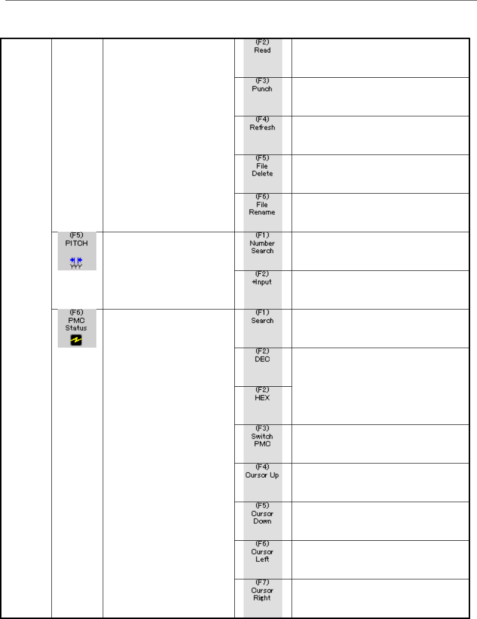
Inputs various data items.
Outputs various data items.
Refreshes the screen display.
Deletes various data files.
Renames various data files.
Displays a specified number.
Pitch
Inputs pitch error data as an incremental
value.
Searches for a specified address.
Switches between decimal display and
hexadecimal display.
Selects a display target PMC.
Moves the cursor to the previous PMC
address.
Moves the cursor to the next PMC
address.
Moves the cursor to the left-hand bit.
PMC Status
Moves the cursor to the right-hand bit.
Contents Summary of Open CNC Basic Operation Package 2 Operators manual
- Page 1FANUC OPEN CNC BASIC OPERATION PACKAGE 2 OPERATOR’S MANUAL B-63924EN/01
- Page 2• No part of this manual may be reproduced in any form. • All specifications and designs are subject to change without notice. The export of this product is subject to the authorization of the government of the country from where the product is exported. In this manual we have tried as much as possi
- Page 3B-63924EN/01 SAFETY PRECAUTIONS SAFETY PRECAUTIONS This manual includes safety precautions for protecting the user and preventing damage to the machine. Precautions are classified into Warning and Caution according to their bearing on safety. Also, supplementary information is described as a Note. R
- Page 4SAFETY PRECAUTIONS B-63924EN/01 GENERAL WARNINGS AND CAUTIONS The warning and caution below provide the precautions related to the use of a CNC. It is essential that these precautions be observed by users to ensure the safe operation of machines equipped with a CNC. WARNING 1 Before operating the ma
- Page 5B-63924EN/01 SAFETY PRECAUTIONS CAUTION NC programs, parameters, and macro variables are stored in nonvolatile memory in the CNC. Usually, they are retained even if the power is turned off. Such data may be deleted by malfunction, however, or it may prove necessary to delete all data from nonvolatil
- Page 6SAFETY PRECAUTIONS B-63924EN/01 WARNINGS AND CAUTIONS RELATING TO BASIC OPERATION PACKAGE 2 Warnings and cautions relating to Basic Operation Package 2 are explained in this manual. Before using the product, read this manual thoroughly to become familiar with the provided Warning, Caution, and Note.
- Page 7B-63924EN/01 PREFACE PREFACE Thank you for purchasing the FANUC Basic Operation Package 2. Basic Operation Package 2 is software that allows the user to perform basic CNC and PMC operations in an Open CNC Microsoft® Windows® environment. Read this manual thoroughly to ensure the correct use of Basic
- Page 8PREFACE B-63924EN/01 BASIC OPERATION PACKAGE 2 FEATURES AND RESTRICTIONS Basic Operation Package 2 has the following features: Features • Basic CNC and PMC operations under Windows provide a more user-friendly operating environment. • A maximum of 10 CNCs can be connected and the operation and displ
- Page 9B-63924EN/01 PREFACE The following restrictions are imposed on Basic Operation Package 2. Restrictions • This software cannot be used with the MMC-IV, a personal computer connected over HSSB Type 1 or Type 2, and Intelligent Terminal Type 1 or Type 2. • This software supports the following CNCs: - T
- Page 10PREFACE B-63924EN/01 CONTENTS OF THE PRODUCT PACKAGE This product package includes the following: • CD-R FANUC Basic Operation Package 2 Microsoft .NET Framework 1.1 README.TXT : Release Note (English version) READMEJ.TXT : Release Note (Japanese version) p-4
- Page 11B-63924EN/01 PREFACE ORGANIZATION OF THIS MANUAL Basic Operation Package 2 can be used as a standard interface provided by FANUC for an Open CNC environment as well as a base with which the user starts customization. Therefore, this manual includes operation sections and customization sections. See
- Page 12PREFACE B-63924EN/01 STANDARD OPERATION 1 SCREEN LAYOUT AND COMMON ITEMS Explains the standard screen layout of Basic Operation Package 2 and the display and operation methods common to all screens. 2 POSITION DISPLAY Explains how to display the current or other positions of the CNC. 3 NC PROGRAM Ex
- Page 13B-63924EN/01 PREFACE APPENDIX APPENDIX A SCREEN-SPECIFIC CNC SETTINGS Explains the CNC settings (options, parameters, and modes) about each screen of Basic Operation Package 2. APPENDIX B CREATING MESSAGE LANGUAGE FILES Explains how to change the message strings displayed on Basic Operation Package
- Page 14PREFACE B-63924EN/01 NOTATION CONVENTIONS The following explains the notation conventions used in this manual: • Menu, command, and screen notations Example Explanation [File] menu Menu names are enclosed in brackets [ ]. [Setting...] Command names are enclosed in brackets [ ]. [Program Edit] screen
- Page 15B-63924EN/01 TABLE OF CONTENTS TABLE OF CONTENTS SAFETY PRECAUTIONS............................................................................s-1 PREFACE ....................................................................................................p-1 1 SETUP..................................
- Page 16TABLE OF CONTENTS B-63924EN/01 2.3.3.12 Deleting a folder from the CNC........................................................................................................... 72 2.3.3.13 Renaming a folder on the CNC..................................................................................
- Page 17B-63924EN/01 TABLE OF CONTENTS 2.4.4.6 Making a custom macro variable empty ............................................................................................ 134 2.4.5 Setting Workpiece Origin Offset..........................................................................135 2.4.5.1 Find
- Page 18TABLE OF CONTENTS B-63924EN/01 2.5.11.10 Displaying PMC data in decimal or hexadecimal.............................................................................. 195 2.6 MESSAGES............................................................................................... 196 2.6.1 Displaying Al
- Page 19B-63924EN/01 TABLE OF CONTENTS 3.5.5.8 DNC Operation Monitor screen-specific definitions......................................................................... 271 3.5.5.9 DNC Schedule Setting screen-specific definitions............................................................................ 2
- Page 20
- Page 21B-63924EN/01 1.SETUP 1 SETUP This chapter explains the environment for operating Basic Operation Package 2 and the method of setup. -1-�
- Page 221.SETUP B-63924EN/01 1.1 OPERATING ENVIRONMENT The operating environment for Basic Operation Package 2 is described below. As hardware, a commercially available personal computer or PANEL i connected with the CNC via HSSB or Ethernet is required. (Pentium III 1 GHz or higher and a memory size of 256
- Page 23B-63924EN/01 1.SETUP 1.2 INSTALLING BASIC OPERATION PACKAGE 2 This section describes how to install Basic Operation Package 2. Procedure 1 For use based on an HSSB connection, install the necessary drivers. For details, refer to the resource note on the drivers disk (A08B-0084-K790) or FOCAS2 driver
- Page 241.SETUP B-63924EN/01 If you want to install Basic Operation Package 2 at the same location as before, select [Repair FANUC Basic Operation Package 2] then click the
button. Basic Operation Package 2 already installed is overwritten automatically. You proceed to step 9. CAUTION If Basic Oper - Page 25B-63924EN/01 1.SETUP (2) The installation of .NET Framework 1.1 is started. (3) Upon completion of .NET Framework 1.1 installation, the screen below appears. Click the
button. 5 The screen below appears. Click the button. -5-� - Page 261.SETUP B-63924EN/01 6 Select the FOCAS2 libraries (HSSB version and Ethernet version) required for connection with the CNC then click the
button. 7 Specify an installation destination folder then click the button. If multiple user names are registered on the personal computer used, se - Page 27B-63924EN/01 1.SETUP By clicking the
button, the size of free disk space can be checked. 8 The screen below appears. Click the button to start the installation of Basic Operation Package 2. -7- - Page 281.SETUP B-63924EN/01 9 Upon normal completion of Basic Operation Package 2 installation, the screen below appears. Click the
button to exit. -8-� - Page 29B-63924EN/01 1.SETUP 1.3 UNINSTALLING BASIC OPERATION PACKAGE 2 This section describes how to uninstall Basic Operation Package 2. Procedure 1 Choose [Start Menu] → [Settings] → [Control Panel] to open the control panel. 2 Open [Add or Remove Programs]. From the currently installed programs, select
- Page 301.SETUP B-63924EN/01 5 Basic Operation Package 2 can also be uninstalled using another method, that is, the installer. Insert the installation CD for Basic Operation Package 2 to start the installer. The screen below appears. 6 Select [Remove FANUC Basic Operation Package 2] then click the
- Page 31B-63924EN/01 1.SETUP 7 Upon completion of uninstallation, the message below appears. Click the
button to exit. - 11 -� - Page 321.SETUP B-63924EN/01 1.4 PROCEDURE AT INITIAL STARTUP When Basic Operation Package 2 is started initially, a connection destination CNC needs to be specified. Moreover, a screen size and display language need to be selected as required. Procedure 1 Choose [Start Menu] → [Programs] → [Basic Operation
- Page 33B-63924EN/01 1.SETUP 1.5 SETTING THE CNC PARAMETERS This section describes how to set the minimum required CNC parameters for operating Basic Operation Package 2 normally. NOTE If the CNC parameters are not set, the writing and display of NC programs and MDI commands cannot be performed normally. NO
- Page 341.SETUP B-63924EN/01 3 Press the display/operation switching key to display the operation keys. 4 Set the following parameters: Meaning Setting TV check No. 0000 bit 0 → 0 Termination of registration with M02, M30, or M99 No. 3201 bit 6 → 1 - 14 -
- Page 35B-63924EN/01 2.STANDARD OPERATION 2 STANDARD OPERATION This chapter describes the method of operation in the standard state (where no screen customization is performed) of Basic Operation Package 2. - 15 -�
- Page 362.STANDARD OPERATION B-63924EN/01 2.1 SCREEN LAYOUT AND COMMON ITEMS This section describes the standard screen layout, and the common display items and operation method of each screen. 2.1.1 Configuration of the Standard Screen The screen of Basic Operation Package 2 consists of a title bar, status
- Page 37B-63924EN/01 2.STANDARD OPERATION Number in Elements making up Description the screen the screen If a communication error occurs, for example, when the power to the ① Title bar connected CNC is turned off, the error code is displayed. CNC status is displayed. The upper row displays alarm state (star
- Page 382.STANDARD OPERATION B-63924EN/01 • Operation key control a) The key controls vertically arranged on the right side of the standard screen are displayed at all times on a 15-inch screen. On a 10.4-inch screen, the key controls are displayed or hidden by using the corresponding soft key (or [Ctrl]+[A
- Page 39B-63924EN/01 2.STANDARD OPERATION 2.1.2 Key Controls and Screen Transition In the standard state, the operation key controls are classified as indicated below. Key control element Description Function keys Keys corresponding to CNC function keys. Each key is used to select a function group for a chi
- Page 402.STANDARD OPERATION B-63924EN/01 The table below indicates the screens displayed when you press the keys of the operation key controls, and also indicates the operable functions on each screen. Function Submenu Screen displayed Operation Function executed key key key Overall Position Resets coordin
- Page 41B-63924EN/01 2.STANDARD OPERATION Machine Modal Actual Speed Distance to go Modal Actual Speed Program Check Searches for an NC program. Searches for a specified sequence number. Current Block/Next Block (program being executed) Program Edit Starts NC program editing. (directory mode) (Switches the
- Page 422.STANDARD OPERATION B-63924EN/01 Moves an NC program selected by [Select] to a specified folder. Condenses an NC program. Sets the attribute of an NC program. Sets the protect level of an NC program with the 8-level protection function. Deletes an NC program. Creates a folder. Renames a folder. Set
- Page 43B-63924EN/01 2.STANDARD OPERATION Replaces a character string in an NC program with another character string. Cuts character strings from an NC program. Copies character strings from an NC program. Pastes character strings cut or copied by [Cut] or [Copy] at a specified location in the NC program. D
- Page 442.STANDARD OPERATION B-63924EN/01 Pastes character strings cut or copied by [Cut] or [Copy] at a specified location in the MDI program. Inserts sequence numbers. Program Check Searches for an MDI program. Searches for a specified sequence number. DNC Operation Monitor DNC Schedule Setting Creates a
- Page 45B-63924EN/01 2.STANDARD OPERATION Timer Confirms the input of a numeric value (writes a numeric value to the CNC). Cancels the input of a numeric value. Tool Offset Switches the type of display data. (Geometry data for a lathe system, or tool length data for a machining center system) Switches the t
- Page 462.STANDARD OPERATION B-63924EN/01 Inputs a custom macro variable counter value. (Sets a relative coordinate.) Clears all custom macro variables to zero. (Local, common 1, common 2) Make a specified custom macro variable empty. Displays a specified number. Work Zero Offset Inputs a workpiece origin o
- Page 47B-63924EN/01 2.STANDARD OPERATION Moves the cursor to the previous parameter number. Moves the cursor to the next parameter number. Moves the cursor to the left-hand bit. Moves the cursor to the right-hand bit. Displays the previous page. Displays the next page. Turns on all bits of bit-type data. T
- Page 482.STANDARD OPERATION B-63924EN/01 Inputs various data items. Outputs various data items. Refreshes the screen display. Deletes various data files. Renames various data files. Pitch Displays a specified number. Inputs pitch error data as an incremental value. PMC Status Searches for a specified addre
- Page 49B-63924EN/01 2.STANDARD OPERATION Displays the previous page. Displays the next page. PMC Alarm PMC Counter Displays a specified number. Selects a display target PMC. PMC Timer Displays a specified number. Selects a display target PMC. PMC Keep Relay Searches for a specified address. Switches betwee
- Page 502.STANDARD OPERATION B-63924EN/01 Moves the cursor to the previous PMC address. Moves the cursor to the next PMC address. Moves the cursor to the left-hand bit. Moves the cursor to the right-hand bit. Displays the previous page. Displays the next page. PMC Data Switches the screen display to the dat
- Page 51B-63924EN/01 2.STANDARD OPERATION Displays the data table with a specified number. Searches for a specified address. Switches between decimal display and hexadecimal display. Confirms the input of a numeric value (writes a numeric value to the CNC). Cancels the input of a numeric value. Turns on bit
- Page 522.STANDARD OPERATION B-63924EN/01 Operator Message Alarm History Deletes alarm history data. Setup Sets the operation and configuration of Basic Operation Package 2. Language Select Setting Selects a display language. Folder Select Setting Selects the reference folder of a screen definition file. Ab
- Page 53B-63924EN/01 2.STANDARD OPERATION 2.1.3 Display of Messages from Connected CNCs Basic Operation Package 2 displays, on a real-time basis, alarm messages and operator messages issued from all connected CNCs. • Display format An alarm message is displayed in red in the following format: [ CNC-number:
- Page 542.STANDARD OPERATION B-63924EN/01 • Method of closing the area for displaying messages from CNCs One of the following two methods can be used to close the message display area: a) Click the
button to the right of the message display area. b) Press the [Enter] key on the keyboard or press the [I - Page 55B-63924EN/01 2.STANDARD OPERATION 2.1.4 Monitoring the Power State of Connected CNCs Basic Operation Package 2 monitors the state of communication with all connected CNCs. If communication is disconnected for a cause such as the power-off state of a CNC, an error is displayed in the following format
- Page 562.STANDARD OPERATION B-63924EN/01 When communication is resumed, for example, because the power to the CNC is turned on, the error display of the title bar and each child screen disappears, and a connection is established again. - 36 -�
- Page 57B-63924EN/01 2.STANDARD OPERATION 2.2 POSITION DISPLAY This section describes how to display positions such as the current position of the CNC. 2.2.1 Overall Position Display The overall positions (relative position, absolute position, machine position, and distance to go) of the CNC are displayed.
- Page 582.STANDARD OPERATION B-63924EN/01 2.2.2 Displaying the Absolute Position The absolute position of the CNC is displayed. Modal information (such as G codes) and actual speed information (actual feedrate and spindle speed) are displayed at the same time. This screen can be displayed by pressing the [P
- Page 59B-63924EN/01 2.STANDARD OPERATION 2.2.3 Displaying the Relative Position The relative position of the CNC is displayed. Modal information (such as G codes) and actual speed information (actual feedrate and spindle speed) are displayed at the same time. This screen can be displayed by pressing the [P
- Page 602.STANDARD OPERATION B-63924EN/01 2.2.3.1 Resetting relative coordinates The relative coordinates of the CNC can be reset to 0. Procedure 1 If the [Relative] screen (or [Overall Position] screen) is currently not displayed, display the [Relative] screen (or [Overall Position] screen) as described in
- Page 61B-63924EN/01 2.STANDARD OPERATION 4 From the list of the coordinate axes, select one or more axes for which the relative coordinates are to be reset. To select all the axes, click the
button. To deselect all the axes, click the button. 5 Clicking the button resets the sele - Page 622.STANDARD OPERATION B-63924EN/01 2.2.3.2 Presetting relative coordinates The relative coordinates of the CNC can be preset to entered values. Procedure 1 If the [Relative] screen (or [Overall Position] screen) is currently not displayed, display the [Relative] screen (or [Overall Position] screen)
- Page 63B-63924EN/01 2.STANDARD OPERATION 4 Select the axis for which the relative coordinate is to be preset, then enter the value to which the relative coordinate is to be preset. 5 Clicking the
button presets the selected relative coordinate. - 43 -� - Page 642.STANDARD OPERATION B-63924EN/01 2.2.3.3 Setting the machine position to the floating reference position The machine position of the CNC can be set to the floating reference position. NOTE To set the floating reference position, the corresponding CNC option is required. Procedure 1 If the [Absolute
- Page 65B-63924EN/01 2.STANDARD OPERATION 4 Select one or more axes for which the machine position is to be set to the floating reference position. To select all the axes, click the
button. To deselect all the axes, click the button. 5 Clicking the button sets the machine position - Page 662.STANDARD OPERATION B-63924EN/01 2.2.3.4 Presetting the workpiece coordinate system The workpiece coordinate system of the CNC can be preset. The absolute coordinate on the preset axis is set as follows: Absolute coordinate value = current absolute coordinate value - the value on the corresponding
- Page 67B-63924EN/01 2.STANDARD OPERATION 4 Select one or more axes for which the workpiece coordinate system is to be preset. To select all the axes, click the
button. To deselect all the axes, click the button. 5 Clicking the button presets the workpiece coordinate system. - 47 - Page 682.STANDARD OPERATION B-63924EN/01 2.2.4 Displaying the Machine Position The machine position of the CNC is displayed. Modal information (such as G codes) and actual speed information (actual feedrate and spindle speed) are displayed at the same time. This screen can be displayed by pressing the [POS
- Page 69B-63924EN/01 2.STANDARD OPERATION 2.2.5 Displaying the Distance to Go The distance to go of the CNC is displayed. Modal information (such as G codes) and actual speed information (actual feedrate and spindle speed) are displayed at the same time. This screen can be displayed by pressing the [POSITIO
- Page 702.STANDARD OPERATION B-63924EN/01 2.3 NC PROGRAM This section explains how to display, edit, and check NC programs stored in the CNC. 2.3.1 Checking the NC Program Currently Being Executed The details of the NC program currently being executed are displayed. The relative position and modal informati
- Page 71B-63924EN/01 2.STANDARD OPERATION 2.3.1.1 Searching for an NC program A search can be made for an NC program. NOTE To search for an NC program, set the following status: • Operation - EDIT mode, or - Stopped in MEMORY mode Procedure 1 If the [Program Check] screen is currently not displayed, display
- Page 722.STANDARD OPERATION B-63924EN/01 2.3.1.2 Searching for a sequence number The currently selected NC program can be searched for a specified sequence number. NOTE Before a search can be made for a sequence number, the sequence number must be inserted in the NC program. Moreover, set the following sta
- Page 73B-63924EN/01 2.STANDARD OPERATION 2.3.2 Displaying the Current and Next Blocks of the NC Program Being Executed Information about the current and next blocks of the NC program being executed is displayed. This screen can be displayed by pressing the [PROGRAM] function key and the [BLOCK] submenu key
- Page 742.STANDARD OPERATION B-63924EN/01 2.3.3 Displaying the NC Program Directory The directory of NC programs on the CNC memory is displayed. Memory use status is displayed at the same time. This screen can be displayed by pressing the [PROGRAM] function key and [EDIT] submenu key. This screen allows you
- Page 75B-63924EN/01 2.STANDARD OPERATION 2.3.3.1 Switching the NC program directory display The display of the [Program Edit] screen can be switched. Procedure 1 If the [Program Edit] screen is currently not displayed, display the [Program Edit] screen as described in Subsection 2.3.3, "Displaying the NC P
- Page 762.STANDARD OPERATION B-63924EN/01 • Attribute display The attributes below are displayed for NC programs and folders. Symbol Description R Editing disabled D Display disabled E Encoded (NC program only) • Protect level The display format of an NC program protect level is "change protect level/output
- Page 77B-63924EN/01 2.STANDARD OPERATION 2.3.3.2 Selecting an NC program to be executed An NC program to be executed can be selected. NOTE To select an NC program to be executed, set the following status: • Operation - EDIT mode, or reset in MEMORY mode Procedure 1 If the [Program Edit] screen is currently
- Page 782.STANDARD OPERATION B-63924EN/01 2.3.3.3 Creating an NC program A new NC program can be created on the CNC. Procedure 1 If the [Program Edit] screen is currently not displayed, display the [Program Edit] screen as described in Subsection 2.3.3, "Displaying the NC Program Directory". 2 Press the dis
- Page 79B-63924EN/01 2.STANDARD OPERATION 2.3.3.4 Deleting an NC program An NC program on the CNC can be deleted. NOTE To delete an NC program, release the protection of the NC program. Moreover, set the following status: • Operation - Stopped Procedure 1 If the [Program Edit] screen is currently not displa
- Page 802.STANDARD OPERATION B-63924EN/01 2.3.3.5 Renaming an NC program An NC program on the CNC can be renamed. NOTE To rename an NC program, release the protection of the NC program. Procedure 1 If the [Program Edit] screen is currently not displayed, display the [Program Edit] screen as described in Sub
- Page 81B-63924EN/01 2.STANDARD OPERATION 2.3.3.6 Copying an NC program An NC program on the CNC can be copied to a specified folder. NOTE To copy an NC program, release the protection of the NC program. Moreover, set the following status: • Operation - EDIT mode Procedure 1 If the [Program Edit] screen is
- Page 822.STANDARD OPERATION B-63924EN/01 7 To assign a new name to the NC program produced by copy operation, enter the new NC program name in the text box. 8 Click the
button. The NC program is copied to the specified folder. - 62 -� - Page 83B-63924EN/01 2.STANDARD OPERATION 2.3.3.7 Moving an NC program An NC program on the CNC can be moved to a specified folder. NOTE To move an NC program, release the protection of the NC program. Moreover, set the following status: • Operation - EDIT mode Procedure 1 If the [Program Edit] screen is cu
- Page 842.STANDARD OPERATION B-63924EN/01 7 To assign a new name to the moved NC program, enter the new NC program name in the text box. 8 Click the
button. The NC program is moved to the specified folder. - 64 -� - Page 85B-63924EN/01 2.STANDARD OPERATION 2.3.3.8 Setting the attribute of an NC program The attribute of an NC program on the CNC can be set. NOTE To set the attribute of an NC program, set the following status: • Operation - Stopped • When the attribute for disabling display is set - Program protection re
- Page 862.STANDARD OPERATION B-63924EN/01 5 Press the operation key to display the [Program Edit - Program Attribute] screen. 6 Check an item to be set then click the
button. - 66 -� - Page 87B-63924EN/01 2.STANDARD OPERATION 2.3.3.9 Setting the protect level of an NC program A protect level can be set for an NC program on the CNC. NOTE To set a protect level for an NC program, the 8-level protection option is required. Moreover, set the following status: • Operation - Stopped Procedure
- Page 882.STANDARD OPERATION B-63924EN/01 5 Press the operation key to display the [Program Edit - Protect Level] screen. The operation level set on the CNC is displayed on this screen. 6 Set the change protect level and output protect level then click the
button. The NC program whose protect level is - Page 89B-63924EN/01 2.STANDARD OPERATION 2.3.3.10 Condensing an NC program An NC program on the CNC can be condensed. NOTE To condense an NC program, release the protection of the NC program. Procedure 1 If the [Program Edit] screen is currently not displayed, display the [Program Edit] screen as described
- Page 902.STANDARD OPERATION B-63924EN/01 2.3.3.11 Creating a folder on the CNC A new folder can be created on the CNC. NOTE To create a folder on the CNC, set the following status: • Operation - Stopped Procedure 1 If the [Program Edit] screen is currently not displayed, display the [Program Edit] screen a
- Page 91B-63924EN/01 2.STANDARD OPERATION 5 Enter a desired folder name then click the
button. - 71 -� - Page 922.STANDARD OPERATION B-63924EN/01 2.3.3.12 Deleting a folder from the CNC A folder on the CNC can be deleted. NOTE To delete a folder from the CNC, set the following status: • Protection of the target folder released • Target folder made empty • Operation - Stopped Procedure 1 If the [Program Edit]
- Page 93B-63924EN/01 2.STANDARD OPERATION 2.3.3.13 Renaming a folder on the CNC A folder on the CNC can be renamed. NOTE To rename a folder on the CNC, release the protection of the folder. Moreover, set the following status: • Operation - Stopped Procedure 1 If the [Program Edit] screen is currently not di
- Page 942.STANDARD OPERATION B-63924EN/01 2.3.3.14 Setting the attribute of a folder on the CNC The attribute of a folder on the CNC can be set. NOTE To set the attribute of a folder on the CNC, set the following status: • Operation - Stopped • When the attribute for disabling display is set - Program prote
- Page 95B-63924EN/01 2.STANDARD OPERATION 2.3.4 Editing an NC Program An NC program on the CNC can be read for editing into the edit screen of Basic Operation Package 2. This screen can be displayed by pressing the [PROGRAM] function key and [EDIT] submenu key then selecting an edit target NC program and pr
- Page 962.STANDARD OPERATION B-63924EN/01 When an edit operation is performed, "Modified" is displayed in the lower right corner of the screen. ↑ [Program Edit] screen (operation keys, "Modified" displayed) - 76 -
- Page 97B-63924EN/01 2.STANDARD OPERATION 2.3.4.1 Writing an NC program back to the CNC The NC program being edited on the edit screen of Basic Operation Package 2 can be written back to the CNC. Procedure 1 If the [Program Edit] screen is currently not displayed, display the [Program Edit] screen as descri
- Page 982.STANDARD OPERATION B-63924EN/01 2.3.4.2 Inserting an NC program from a disk The NC program stored in a file on the hard disk (or another external memory unit) can be inserted into the NC program being edited. Procedure 1 If the [Program Edit] screen is currently not displayed, display the [Program
- Page 99B-63924EN/01 2.STANDARD OPERATION 2.3.4.3 Writing an NC program to a disk The entire NC program being edited can be written as a file to the hard disk (or another external memory unit). Procedure 1 If the [Program Edit] screen is currently not displayed, display the [Program Edit] screen as describe
- Page 1002.STANDARD OPERATION B-63924EN/01 2.3.4.4 Inserting sequence numbers into an NC program In the NC program being edited, sequence numbers can be automatically inserted for newly created lines. Procedure 1 If the [Program Edit] screen is currently not displayed, display the [Program Edit] screen as de
- Page 101B-63924EN/01 2.STANDARD OPERATION Explanation The initial values of the [Program Edit - Insert Sequence Number] screen can be set using the following parameters: Meaning Setting Enabling automatic insertion No. 0000 bit 5 → 1 Increment No. 3216 - 81 -
- Page 1022.STANDARD OPERATION B-63924EN/01 2.3.4.5 Finding a character string in a NC program A search can be made for a specified character string in the NC program being edited. Procedure 1 If the [Program Edit] screen is currently not displayed, display the [Program Edit] screen as described in Subsection
- Page 103B-63924EN/01 2.STANDARD OPERATION 2.3.4.6 Replacing a character string in an NC program In the NC program being edited, a specified character string can be found and replaced with another character string. Procedure 1 If the [Program Edit] screen is currently not displayed, display the [Program Edit
- Page 1042.STANDARD OPERATION B-63924EN/01 2.3.4.7 Displaying the top/end of an NC program The top or end of the NC program being edited can be displayed. Procedure 1 If the [Program Edit] screen is currently not displayed, display the [Program Edit] screen as described in Subsection 2.3.4, "Editing an NC Pr
- Page 105B-63924EN/01 2.STANDARD OPERATION 2.3.4.8 Entering a coordinate value into an NC program The current absolute coordinate value can be entered into the NC program being edited. NOTE The playback option is required to enter a coordinate value into an NC program. Change the CNC operating mode from the
- Page 1062.STANDARD OPERATION B-63924EN/01 2.3.4.9 Stamping the machining time The machining time for an executed NC program can be inserted as a comment into the NC program being edited. NOTE The option for the machining time stamp function is required for stamping the machining time. When the machining tim
- Page 107B-63924EN/01 2.STANDARD OPERATION 2.3.4.10 Cutting character strings from an NC program Selected character strings can be cut from the NC program being edited. Procedure 1 If the [Program Edit] screen is currently not displayed, display the [Program Edit] screen as described in Subsection 2.3.4, "Ed
- Page 1082.STANDARD OPERATION B-63924EN/01 2.3.4.11 Copying character strings from an NC program Selected character strings can be copied from the NC program being edited. Procedure 1 If the [Program Edit] screen is currently not displayed, display the [Program Edit] screen as described in Subsection 2.3.4,
- Page 109B-63924EN/01 2.STANDARD OPERATION 2.3.4.12 Pasting character strings to an NC program In the NC program being edited, character strings cut or copied by [Cut] or [Copy] can be pasted at a specified position. Procedure 1 If the [Program Edit] screen is currently not displayed, display the [Program Ed
- Page 1102.STANDARD OPERATION B-63924EN/01 2.3.5 Editing an MDI Program An MDI program can be edited on Basic Operation Package 2. This screen can be displayed by pressing the [PROGRAM] function key and [MDI] submenu key. An MDI program can be edited by moving the cursor to a character string to be edited. W
- Page 111B-63924EN/01 2.STANDARD OPERATION 2.3.5.1 Finding a character string in an MDI program A search can be made for a specified character string in the MDI program being edited. Procedure 1 If the [MDI Program] screen is currently not displayed, display the [MDI Program] screen as described in Subsectio
- Page 1122.STANDARD OPERATION B-63924EN/01 2.3.5.2 Replacing a character string in an MDI program In the MDI program being edited, a specified character string can be found and replaced with another character string. Procedure 1 If the [MDI Program] screen is currently not displayed, display the [MDI Program
- Page 113B-63924EN/01 2.STANDARD OPERATION 2.3.5.3 Displaying the top/end of an MDI program The top or end of the MDI program being edited can be displayed. Procedure 1 If the [MDI Program] screen is currently not displayed, display the [MDI Program] screen as described in Subsection 2.3.5, "Editing an MDI P
- Page 1142.STANDARD OPERATION B-63924EN/01 2.3.5.5 Cutting character strings from an MDI program Selected character strings can be cut from the MDI program being edited. Procedure 1 If the [MDI Program] screen is currently not displayed, display the [MDI Program] screen as described in Subsection 2.3.5, "Edi
- Page 115B-63924EN/01 2.STANDARD OPERATION 2.3.5.7 Pasting character strings to an MDI program In the MDI program being edited, character strings cut or copied by [Cut] or [Copy] can be pasted at a specified position. Procedure 1 If the [MDI Program] screen is currently not displayed, display the [MDI Progra
- Page 1162.STANDARD OPERATION B-63924EN/01 2.3.5.8 Inserting sequence numbers into an MDI program In the MDI program being edited, sequence numbers can be automatically inserted for newly created lines. Procedure 1 If the [MDI Program] screen is currently not displayed, display the [MDI Program] screen as de
- Page 117B-63924EN/01 2.STANDARD OPERATION 2.3.6 DNC Schedule Operation In DNC schedule operation, NC programs are prepared on the hard disk of the personal computer, and data such as the names of programs, the order of operation, and the number of repeats is stored on a file called a schedule file beforehan
- Page 1182.STANDARD OPERATION B-63924EN/01 2.3.6.1 Executing a schedule operation A DNC schedule operation can be performed as described below. Procedure 1 Prepare NC programs for schedule operation on the hard disk of the personal computer. (See Subsection 2.3.6.2, "NC program for schedule operation".) 2 Cr
- Page 119B-63924EN/01 2.STANDARD OPERATION 2.3.6.2 NC program for schedule operation An NC program for DNC operation to be prepared on the hard disk of the personal computer must have the following format: • File name - 4-digit number + extension "TXT" • File format - The NC program must start with {LF} or %
- Page 1202.STANDARD OPERATION B-63924EN/01 2.3.6.3 Setting a schedule operation Settings can be made for a DNC schedule operation. This screen can be displayed by pressing the [PROGRAM] function key and [DNC SCHEDUL] submenu key. NOTE During DNC operation, the schedule setting screen cannot be operated. - 10
- Page 121B-63924EN/01 2.STANDARD OPERATION 2.3.6.4 Creating a schedule file A schedule file for setting the file names of NC programs to be used for DNC schedule operation, the order of operation, and the number of repeats can be created. Procedure 1 If the [DNC Schedule Setting] screen is currently not disp
- Page 1222.STANDARD OPERATION B-63924EN/01 6 Press the operation key to display the [DNC Schedule Setting - Add Program] screen. 7 Select an NC program to be used for schedule operation then click the
- Page 123B-63924EN/01 2.STANDARD OPERATION 9 Press the operation key to display the [DNC Schedule Setting - Repeat Count] screen. 10 Enter the number of operation repeats then click the
button. NOTE If 0 is entered in Repeat Count, the NC program is not executed. If a negative value is entered in Repeat - Page 1242.STANDARD OPERATION B-63924EN/01 2.3.6.5 Opening an existing schedule file A schedule file created previously can be opened. Procedure 1 If the [DNC Schedule Setting] screen is currently not displayed, display the [DNC Schedule Setting] screen as described in Subsection 2.3.6.3, "Setting a schedule
- Page 125B-63924EN/01 2.STANDARD OPERATION 2.3.6.6 Saving a schedule file under an alias The currently open schedule file can be saved under an alias. Procedure 1 If the [DNC Schedule Setting] screen is currently not displayed, display the [DNC Schedule Setting] screen as described in Subsection 2.3.6.3, "Se
- Page 1262.STANDARD OPERATION B-63924EN/01 2.3.7 DNC Subprogram Call Operation In DNC subprogram call operation, a main program is prepared on the CNC, and NC programs to be called as subprograms are prepared on the personal computer. When the subprogram call block M198Pxxxx is executed in memory operation o
- Page 127B-63924EN/01 2.STANDARD OPERATION 2.3.7.1 Executing a subprogram call operation A DNC subprogram call operation can be performed as described below. Procedure 1 Prepare NC programs for subprogram call operation on the hard disk of the personal computer. 2 (See Subsection 2.3.7.2, "NC program for sub
- Page 1282.STANDARD OPERATION B-63924EN/01 2.3.7.2 NC program for subprogram call operation An NC program for subprogram call operation to be prepared on the hard disk of the personal computer must have the following format: • File name - 4-digit number + extension "TXT" • File format - The NC program must s
- Page 129B-63924EN/01 2.STANDARD OPERATION 2.3.7.3 Specifying a folder storing subprograms The folder storing NC programs to be used for a DNC subprogram call operation can be specified. This screen can be displayed by pressing the [PROGRAM] function key and [DNC SUBPRG] submenu key. NOTE During DNC operatio
- Page 1302.STANDARD OPERATION B-63924EN/01 3 Press the operation key to display the [DNC Subprogram Call - Folder Setting] screen. 4 Select a folder storing NC programs then click the
button. A list of the files with the extension TXT stored in the specified folder is displayed. - 110 -� - Page 131B-63924EN/01 2.STANDARD OPERATION 2.3.8 Monitoring the Execution Progress of DNC Operation After a DNC schedule operation or DNC subprogram call operation is started, the execution progress of DNC operation can be checked on the [DNC Operation Monitor] screen. This screen can be displayed by pressin
- Page 1322.STANDARD OPERATION B-63924EN/01 Explanation • Display data - Operating mode The mode of automatic operation is indicated. Indication Meaning DNC Indicates that the DNC operation mode is set. MEMORY Indicates that the MEMORY operation mode of the CNC is set. - Status The state of automatic operatio
- Page 133B-63924EN/01 2.STANDARD OPERATION - Schedule In a DNC schedule operation, a list of the NC programs registered in the schedule file and their transfer statuses are displayed. If "Loop" is indicated in Req. repeat, "-" is indicated when the repeat count exceeds 9999. NOTE • The execution progress sta
- Page 1342.STANDARD OPERATION B-63924EN/01 2.4 SETTING This section describes how to set various types of data. 2.4.1 Setting of Settings Settings such as "TV check" and "Punch code" can be set. This screen can be displayed by pressing the [SETTING] function key and [HANDY] submenu key. NOTE To set settings,
- Page 135B-63924EN/01 2.STANDARD OPERATION On this screen, the following data items can be set: Name Description Parameter write Specify whether to enable parameter write. When the check box is checked, parameter write is enabled. TV check Specify whether to execute a TV check. When the check box is checked,
- Page 1362.STANDARD OPERATION B-63924EN/01 Procedure 1 If the [Handy] screen is currently not displayed, display the [Handy] screen by pressing the [SETTING] function key and [HANDY] submenu key. 2 Press the display/operation switching key to display the operation keys. 3 Select an item to be set. 4 The valu
- Page 137B-63924EN/01 2.STANDARD OPERATION 2.4.2 Setting Operating Time, Parts Count, and Timer Data items such as operating time, required parts, and timer can be set. This screen can be displayed by pressing the [SETTING] function key and [TIMER] submenu key. NOTE To set the operating time, parts count, an
- Page 1382.STANDARD OPERATION B-63924EN/01 On this screen, the following data items can be displayed and set: Name Description Parts total Indicates a cumulative value counted when M02, M30, or another M code specified in a parameter is executed. This field of the screen provides an indication only and does
- Page 139B-63924EN/01 2.STANDARD OPERATION Procedure 1 If the [Timer] screen is currently not displayed, display the [Timer] screen by pressing the [SETTING] function key and [TIMER] submenu key. 2 Press the display/operation switching key to display the operation keys. 3 Select an item to be set. 4 Enter a
- Page 1402.STANDARD OPERATION B-63924EN/01 2.4.3 Setting Tool Offset Tool offset values can be displayed and set. This screen can be displayed by pressing the [SETTING] function key and [OFFSET] submenu key. The type of offset value that can be set depends on the CNC option. For details, refer to the operato
- Page 141B-63924EN/01 2.STANDARD OPERATION Procedure 1 If the [Tool Offset] screen is currently not displayed, display the [Tool Offset] screen by pressing the [SETTING] function key and [OFFSET] submenu key. 2 Press the display/operation switching key to display the operation keys. 3 Select a tool offset da
- Page 1422.STANDARD OPERATION B-63924EN/01 2.4.3.1 Switching the type of tool offset data A type of tool offset data to be set and displayed can be selected. Procedure 1 If the [Tool Offset] screen is currently not displayed, display the [Tool Offset] screen as described in Subsection 2.4.3, "Setting Tool Of
- Page 143B-63924EN/01 2.STANDARD OPERATION 2.4.3.2 Finding a tool offset data number The tool offset data of a specified number can be displayed. Procedure 1 If the [Tool Offset] screen is currently not displayed, display the [Tool Offset] screen as described in Subsection 2.4.3, "Setting Tool Offset". 2 Pre
- Page 1442.STANDARD OPERATION B-63924EN/01 2.4.3.3 Entering an increment for tool offset data An increment can be entered for tool offset data. Procedure 1 If the [Tool Offset] screen is currently not displayed, display the [Tool Offset] screen as described in Subsection 2.4.3, "Setting Tool Offset". 2 Press
- Page 145B-63924EN/01 2.STANDARD OPERATION 2.4.3.4 Entering a counter value for tool offset data A coordinate value displayed on the [Relative] screen can be set for tool offset data. Procedure 1 If the [Tool Offset] screen is currently not displayed, display the [Tool Offset] screen as described in Subsecti
- Page 1462.STANDARD OPERATION B-63924EN/01 2.4.3.5 Entering a measured value for tool offset data NOTE The function for entering a measured value is supported only for lathe systems. Tool offset data can be set based on a measured value. The following value is set as a tool offset value: Tool offset value =
- Page 147B-63924EN/01 2.STANDARD OPERATION 2.4.3.6 Clearing all tool offset data to zero All set tool offset data can be cleared to 0. NOTE This command is valid when bit 4 of parameter No. 3205 is set to 0. Procedure 1 If the [Tool Offset] screen is currently not displayed, display the [Tool Offset] screen
- Page 1482.STANDARD OPERATION B-63924EN/01 2.4.4 Setting a Custom Macro Variable The value of a custom macro variable can be displayed and set. This screen can be displayed by pressing the [SETTING] function key and [MACRO] submenu key. WARNING Incorrect use or setting of a custom macro variable may result i
- Page 149B-63924EN/01 2.STANDARD OPERATION Procedure 1 If the [Custom Macro] screen is currently not displayed, display the [Custom Macro] screen by pressing the [SETTING] function key and [MACRO] submenu key. 2 Select data to be set. 3 Enter a desired value through the keyboard or MDI panel. Press the [Ente
- Page 1502.STANDARD OPERATION B-63924EN/01 2.4.4.1 Switching the type of custom macro variable A type of custom macro variables to be displayed and set can be selected. Procedure 1 If the [Custom Macro] screen is currently not displayed, display the [Custom Macro] screen as described in Subsection 2.4.4, "Se
- Page 151B-63924EN/01 2.STANDARD OPERATION 2.4.4.2 Finding a custom macro variable number The custom macro variable of a specified number can be displayed. Procedure 1 If the [Custom Macro] screen is currently not displayed, display the [Custom Macro] screen as described in Subsection 2.4.4, "Setting a Custo
- Page 1522.STANDARD OPERATION B-63924EN/01 2.4.4.3 Entering an increment for a custom macro variable An increment can be entered for the value of a custom macro variable. Procedure 1 If the [Custom Macro] screen is currently not displayed, display the [Custom Macro] screen as described in Subsection 2.4.4, "
- Page 153B-63924EN/01 2.STANDARD OPERATION 2.4.4.4 Entering a counter value for a custom macro variable A coordinate value displayed on the [Relative] screen can be set for the value of a custom macro variable. Procedure 1 If the [Custom Macro] screen is currently not displayed, display the [Custom Macro] sc
- Page 1542.STANDARD OPERATION B-63924EN/01 2.4.4.5 Clearing all custom macro variables to zero All custom macro variables of the type currently displayed are cleared to zero. Procedure 1 If the [Custom Macro] screen is currently not displayed, display the [Custom Macro] screen as described in Subsection 2.4.
- Page 155B-63924EN/01 2.STANDARD OPERATION 2.4.5 Setting Workpiece Origin Offset A workpiece origin offset value can be set based on the position of the workpiece origin viewed from the machine zero point. This screen can be displayed by pressing the [SETTING] function key and [WORK OFS] submenu key. WARNING
- Page 1562.STANDARD OPERATION B-63924EN/01 Procedure 1 If the [Work Zero Offset] screen is currently not displayed, display the [Work Zero Offset] screen by pressing the [SETTING] function key and [WORK OFS] submenu key. 2 Press the display/operation switching key to display the operation keys. 3 Select work
- Page 157B-63924EN/01 2.STANDARD OPERATION 2.4.5.1 Finding a workpiece origin offset data number The workpiece origin offset data of a specified number can be displayed. Procedure 1 If the [Work Zero Offset] screen is currently not displayed, display the [Work Zero Offset] screen as described in Subsection 2
- Page 1582.STANDARD OPERATION B-63924EN/01 2.4.5.2 Entering a measured value for workpiece origin offset data Workpiece origin offset data can be set based on a measured value. The following value is set as a workpiece origin offset value: Workpiece origin offset value = Machine coordinate value - Measured v
- Page 159B-63924EN/01 2.STANDARD OPERATION 2.4.5.3 Entering an increment for workpiece origin offset data An increment can be entered for workpiece origin offset data. Procedure 1 If the [Work Zero Offset] screen is currently not displayed, display the [Work Zero Offset] screen as described in Subsection 2.4
- Page 1602.STANDARD OPERATION B-63924EN/01 2.4.6 Setting a Workpiece Coordinate System Shift A workpiece coordinate system shift value can be set. This screen can be displayed by pressing the [SETTING] function key and [W.Shift] submenu key. WARNING Setting an incorrect workpiece coordinate system shift valu
- Page 161B-63924EN/01 2.STANDARD OPERATION • [Relative] and [Absolute] screens Relative position and absolute position data is displayed. For operation, see Section 2.2, "POSITION DISPLAY". Procedure 1 If the [Work Shift] screen is currently not displayed, display the [Work Shift] screen by pressing the [SET
- Page 1622.STANDARD OPERATION B-63924EN/01 2.4.6.1 Entering an increment for workpiece coordinate system shift data An increment can be entered for a workpiece coordinate system shift value. Procedure 1 If the [Work Shift] screen is currently not displayed, display the [Work Shift] screen as described in Sub
- Page 163B-63924EN/01 2.STANDARD OPERATION 2.5 SYSTEM This section describes how to display and set system-related information, and how to input and output different types of data. 2.5.1 Displaying Parameters The values of parameters for defining the machine specifications and functions can be displayed and
- Page 1642.STANDARD OPERATION B-63924EN/01 Procedure 1 If the [Parameter] screen is currently not displayed, display the [Parameter] screen by pressing the [SYSTEM] function key and [PARAM] submenu key. 2 Press the display/operation switching key to display the operation keys. a) By pressing the operation ke
- Page 165B-63924EN/01 2.STANDARD OPERATION 2.5.1.1 Finding a parameter number The parameter of a specified number can be displayed. Procedure 1 If the [Parameter] screen is currently not displayed, display the [Parameter] screen as described in Subsection 2.5.1, "Displaying Parameters". 2 Press the display/o
- Page 1662.STANDARD OPERATION B-63924EN/01 2.5.1.2 Setting parameters A parameter can be set. NOTE To set a parameter, set the following status: • Setting - Enable Parameter Write. • Operation - Emergency stop, or - Stopped or paused in MDI mode For the method of setting of settings, see Subsection 2.4.1, "S
- Page 167B-63924EN/01 2.STANDARD OPERATION 2.5.1.3 Enabling parameter write Whether to enable the setting "Parameter Write" can be set. This setting is also referred to as PWE (Parameter Write Enabled). NOTE To enable parameter write, set the following status: • Operation - Emergency stop, or - Stopped or pa
- Page 1682.STANDARD OPERATION B-63924EN/01 2.5.2 Displaying the Diagnosis Screen Diagnostic data indicating machine state can be displayed. This screen can be displayed by pressing the [SYSTEM] function key and [DIAG] submenu key. Procedure 1 If the [Diagnosis] screen is currently not displayed, display the
- Page 169B-63924EN/01 2.STANDARD OPERATION 2.5.2.1 Finding a diagnostic data number The diagnostic data of a specified number can be displayed. Procedure 1 If the [Diagnosis] screen is currently not displayed, display the [Diagnosis] screen as described in Subsection 2.5.2, "Displaying the Diagnosis Screen".
- Page 1702.STANDARD OPERATION B-63924EN/01 2.5.3 Displaying the System Configuration The following system configuration data can be displayed. Name Description Hardware Hardware names, ID-1, ID-2, and slot numbers are displayed. Software Information about the control software of the system and added software
- Page 171B-63924EN/01 2.STANDARD OPERATION 2.5.3.1 Outputting system configuration data to a file System configuration data can be output in text format to a file. Procedure 1 If the [System Configuration] screen is currently not displayed, display the [System Configuration] screen as described in Subsection
- Page 1722.STANDARD OPERATION B-63924EN/01 2.5.4 Inputting/Outputting Data Various data items can be transferred between the CNC and Basic Operation Package 2. Moreover, a data file can be deleted or renamed. This screen can be displayed by pressing the [SYSTEM] function key and [DATA IO] submenu key. The fo
- Page 173B-63924EN/01 2.STANDARD OPERATION 2.5.4.1 Setting parameters for input/output Parameters for input/output of various types of data can be set. Procedure 1 If the [Data I/O] screen is currently not displayed, display the [Data I/O] screen as described in Subsection 2.5.4, "Inputting/Outputting Data".
- Page 1742.STANDARD OPERATION B-63924EN/01 • I/O data - TV check A blank code for TV check is inserted into the data block. When this item is checked, TV check is enabled. - CTV CTV is enabled when TV check is turned on. When this item is checked, TV check in a comment is canceled. - 154 -
- Page 175B-63924EN/01 2.STANDARD OPERATION 2.5.4.2 Displaying a list of various types of data files A list of various types of data files can be displayed. Procedure 1 If the [Data I/O] screen is currently not displayed, display the [Data I/O] screen as described in Subsection 2.5.4, "Inputting/Outputting Da
- Page 1762.STANDARD OPERATION B-63924EN/01 2.5.4.3 Entering various types of data Various types of data can be input from files. The input of data means the transfer of data from Basic Operation Package 2 to the CNC. WARNING • Before starting the machine to machine a workpiece after input of data (NC program
- Page 177B-63924EN/01 2.STANDARD OPERATION Procedure 1 If the [Data I/O] screen is currently not displayed, display the [Data I/O] screen as described in Subsection 2.5.4, "Inputting/Outputting Data". 2 Press the display/operation switching key to display the operation keys. 3 Set a folder to be displayed as
- Page 1782.STANDARD OPERATION B-63924EN/01 7 Upon completion of input, the screen shown below is displayed. NOTE • When the parameters output from a CNC are to be entered into another CNC, ensure in advance that the number of axes, option selection states, and parameters match. For the CNC parameter for the
- Page 179B-63924EN/01 2.STANDARD OPERATION 2.5.4.4 Outputting various types of data Various types of data can be output to files. The output of data means the transfer of data from the CNC to Basic Operation Package 2. Procedure 1 If the [Data I/O] screen is currently not displayed, display the [Data I/O] sc
- Page 1802.STANDARD OPERATION B-63924EN/01 8 Upon completion of output, the screen shown below is displayed. NOTE If an existing output file name is specified, a screen is displayed to check whether you allow the existing file to be overwritten. If you do not allow the existing file to be overwritten, the ou
- Page 181B-63924EN/01 2.STANDARD OPERATION 2.5.4.5 Deleting various types of data files Various types of data files can be deleted. Procedure 1 If the [Data I/O] screen is currently not displayed, display the [Data I/O] screen as described in Subsection 2.5.4, "Inputting/Outputting Data". 2 Press the display
- Page 1822.STANDARD OPERATION B-63924EN/01 6 Click the
button. All of the selected files are deleted. NOTE This function cannot delete an NC program on the CNC. - 162 -� - Page 183B-63924EN/01 2.STANDARD OPERATION 2.5.4.6 Renaming various data files Various data files can be renamed. Procedure 1 If the [Data I/O] screen is currently not displayed, display the [Data I/O] screen as described in Subsection 2.5.4, "Inputting/Outputting Data". 2 Press the display/operation switchi
- Page 1842.STANDARD OPERATION B-63924EN/01 2.5.5 Setting Pitch Error Compensation Data Pitch error compensation data can be set. This screen can be displayed by pressing the [SYSTEM] function key and [PITCH] submenu key. WARNING Pitch error compensation data is set to match the characteristics of the machine
- Page 185B-63924EN/01 2.STANDARD OPERATION 2.5.5.1 Finding a pitch error compensation data number The pitch error compensation data of a specified number can be displayed. Procedure 1 If the [Pitch] screen is currently not displayed, display the [Pitch] screen as described in Subsection 2.5.5, "Setting Pitch
- Page 1862.STANDARD OPERATION B-63924EN/01 2.5.5.2 Entering an increment for pitch error compensation data An increment can be entered for pitch error compensation data. Procedure 1 If the [Pitch] screen is currently not displayed, display the [Pitch] screen as described in Subsection 2.5.5, "Setting Pitch E
- Page 187B-63924EN/01 2.STANDARD OPERATION 2.5.6 Displaying PMC Status PMC status can be displayed. This screen can be displayed by pressing the [SYSTEM] function key and [PMC Status] submenu key. The screen displays PMC addresses and their statuses. A signal displayed in green is active. Procedure 1 If the
- Page 1882.STANDARD OPERATION B-63924EN/01 c) Select a bit by pressing the operation key or , or the [←] or [→] key on the keyboard or MDI panel. 2.5.6.1 Finding a PMC status address The PMC status at a specified address can be displayed. Procedure 1 If the [PMC Status] screen is currently not displayed, dis
- Page 189B-63924EN/01 2.STANDARD OPERATION 2.5.6.2 Displaying PMC status data in decimal or hexadecimal PMC status data display can be switched between decimal display and hexadecimal display. Procedure 1 If the [PMC Status] screen is currently not displayed, display the [PMC Status] screen as described in S
- Page 1902.STANDARD OPERATION B-63924EN/01 2.5.6.3 Switching among PMC status paths The display target PMC path can be switched. NOTE This function is enabled when multiple PMC paths are used. Procedure 1 If the [PMC Status] screen is currently not displayed, display the [PMC Status] screen as described in S
- Page 191B-63924EN/01 2.STANDARD OPERATION 2.5.7 Displaying PMC Alarms The alarms issued from all PMC paths can be displayed. This screen can be displayed by pressing the [SYSTEM] function key and [PMC Alarm] submenu key. For the meaning of each PMC alarm message, refer to the operator's manual of each PMC.
- Page 1922.STANDARD OPERATION B-63924EN/01 2.5.8 Setting a PMC Counter The value of a PMC counter can be displayed and set. This screen can be displayed by pressing the [SYSTEM] function key and [PMC Counter] submenu key. • PMC counter The address, preset value, and current value of a PMC counter are display
- Page 193B-63924EN/01 2.STANDARD OPERATION 2.5.8.1 Finding a PMC counter number The PMC counter data of a specified number can be displayed. Procedure 1 If the [PMC Counter] screen is currently not displayed, display the [PMC Counter] screen as described in Subsection 2.5.8, "Setting a PMC Counter". 2 Press
- Page 1942.STANDARD OPERATION B-63924EN/01 2.5.8.2 Switching among PMC counter paths The display/setting target PMC path can be switched. NOTE This function is enabled when multiple PMC paths are used. Procedure 1 If the [PMC Counter] screen is currently not displayed, display the [PMC Counter] screen as des
- Page 195B-63924EN/01 2.STANDARD OPERATION 2.5.9 Setting a PMC Timer The value of a PMC timer can be displayed and set. This screen can be displayed by pressing the [SYSTEM] function key and [PMC Timer] submenu key. • PMC timer The address, timer value, and accuracy of a PMC timer are displayed. Set a value
- Page 1962.STANDARD OPERATION B-63924EN/01 b) (When the accuracy is "10") A timer value can be displayed/set in steps of 10 milliseconds. When the specified value is not a multiple of 10, the value is rounded to the next lower multiple of 10. c) (When the accuracy is "100") A timer value can be displayed/set
- Page 197B-63924EN/01 2.STANDARD OPERATION 2.5.9.1 Finding a PMC timer number The PMC timer data of a specified number can be displayed. Procedure 1 If the [PMC Timer] screen is currently not displayed, display the [PMC Timer] screen as described in Subsection 2.5.9, "Setting a PMC Timer". 2 Press the displa
- Page 1982.STANDARD OPERATION B-63924EN/01 2.5.9.2 Switching among PMC timer paths The display/setting target PMC path can be switched. NOTE This function is enabled when multiple PMC paths are used. Procedure 1 If the [PMC Timer] screen is currently not displayed, display the [PMC Timer] screen as described
- Page 199B-63924EN/01 2.STANDARD OPERATION 2.5.10 Displaying a PMC Keep Relay The value of a PMC keep relay can be displayed and set. This screen can be displayed by pressing the [SYSTEM] function key and [PMC Relay] submenu key. • PMC keep relay An address and its on/off state are displayed. When a check bo
- Page 2002.STANDARD OPERATION B-63924EN/01 c) The screen display can be moved by pressing the operation key or , the [PageUp] or [PageDown] key on the keyboard, or the [↑PAGE] or [↓PAGE] key on the MDI panel. 2.5.10.1 Finding a PMC keep relay address The PMC keep relay data of a specified address can be disp
- Page 201B-63924EN/01 2.STANDARD OPERATION 2.5.10.2 Displaying PMC keep relay data in decimal or hexadecimal PMC keep relay data display can be switched between decimal display and hexadecimal display. Procedure 1 If the [PMC Keep Relay] screen is currently not displayed, display the [PMC Keep Relay] screen
- Page 2022.STANDARD OPERATION B-63924EN/01 2.5.10.3 Setting a PMC keep relay NOTE To set a PMC keep relay, set the following status: • Operation - Emergency stop, or - Reset in MDI mode Procedure 1 If the [PMC Keep Relay] screen is currently not displayed, display the [PMC Keep Relay] screen as described in
- Page 203B-63924EN/01 2.STANDARD OPERATION 2.5.10.4 Switching among PMC keep relay paths The display/setting target PMC path can be switched. NOTE This function is enabled when multiple PMC paths are used. Procedure 1 If the [PMC Keep Relay] screen is currently not displayed, display the [PMC Keep Relay] scr
- Page 2042.STANDARD OPERATION B-63924EN/01 2.5.11 Setting PMC Data PMC data can be displayed and set by using two-layer screens. The screen of the first layer is a "table control data" screen used to divide PMC data into groups and define the start address, the number of data items, type, and so forth of eac
- Page 205B-63924EN/01 2.STANDARD OPERATION 2.5.11.1 Changing the number of groups of PMC data The total number of group tables can be set on the table control data screen. Procedure 1 If the [PMC Data] screen is currently not displayed, display the [PMC Data] screen as described in Subsection 2.5.11, "Settin
- Page 2062.STANDARD OPERATION B-63924EN/01 2.5.11.2 Setting the table control data of PMC data The items of each group table can be set on the table control data screen. Procedure 1 If the [PMC Data] screen is currently not displayed, display the [PMC Data] screen as described in Subsection 2.5.11, "Setting
- Page 207B-63924EN/01 2.STANDARD OPERATION • Type Select a PMC data type from the following: 0: BYTE type 1: WORD type 2: DWORD type 3: BIT type • Data Set the number of PMC data items in a group table. 2.5.11.3 Finding a group number of PMC data The group table of a specified number can be displayed on the
- Page 2082.STANDARD OPERATION B-63924EN/01 2.5.11.4 Initializing the table control data of PMC data The table control data of the PMC path currently displayed can be initialized on the table control data screen. All of the contents of the set group tables are deleted. Procedure 1 If the [PMC Data] screen is
- Page 209B-63924EN/01 2.STANDARD OPERATION 2.5.11.5 Switching among PMC data paths The display/setting target PMC path can be switched on the table control data screen. NOTE This function is enabled when multiple PMC paths are used. Procedure 1 If the [PMC Data] screen is currently not displayed, display the
- Page 2102.STANDARD OPERATION B-63924EN/01 2.5.11.6 Displaying a data table of PMC data The screen display can be switched to the screen used to display and set the PMC data values of the group table where the cursor is currently placed on the table control data screen. This screen is referred to as the "dat
- Page 211B-63924EN/01 2.STANDARD OPERATION NOTE Before the data table of the PMC data can be displayed, table control data must be set. For the method of setting table control data, see Subsection 2.5.11.2, "Setting the table control data of PMC data". Procedure 1 If the [PMC Data] screen is currently not di
- Page 2122.STANDARD OPERATION B-63924EN/01 Explanation • Group No., Mode, Type, Protect Information set in the group table about the PMC data being displayed is indicated. • Address, Data A PMC address and its value are displayed. An address is displayed as described below, depending on the type of the group
- Page 213B-63924EN/01 2.STANDARD OPERATION 2.5.11.7 Displaying a data table by specifying a PMC data group number On the data table screen, the screen display can be switched to the data table of a specified group number. This function can display the data table of an arbitrary group without returning to the
- Page 2142.STANDARD OPERATION B-63924EN/01 2.5.11.9 Setting data tables of PMC data Each PMC data item can be set on the data table screen. Procedure 1 If the [PMC Data] screen does not display a data table, display a desired data table on the [PMC Data] screen as described in Subsection 2.5.11.6, "Displayin
- Page 215B-63924EN/01 2.STANDARD OPERATION 2.5.11.10 Displaying PMC data in decimal or hexadecimal PMC data value display can be switched between decimal display and hexadecimal display on the data table screen. NOTE This function is enabled only on the data table screen of the BIT type. Procedure 1 If the [
- Page 2162.STANDARD OPERATION B-63924EN/01 2.6 MESSAGES This section explains how to display alarm messages and other messages. 2.6.1 Displaying Alarm Messages Alarm messages currently issued can be displayed. This screen can be displayed by pressing the [MESSAGE] function key and [ALARM] submenu key. For th
- Page 217B-63924EN/01 2.STANDARD OPERATION 2.6.2 Displaying Operator Messages Operator messages currently issued can be displayed. This screen can be displayed by pressing the [MESSAGE] function key and [OPERATOR] submenu key. Operator messages are usually displayed and set to match each machine. So, the tex
- Page 2182.STANDARD OPERATION B-63924EN/01 2.6.3 Displaying the Alarm Message History The history of alarm messages issued so far can be displayed. This screen can be displayed by pressing the [MESSAGE] function key and [HISTORY] submenu key. For the meanings of alarm messages, refer to the operator's manual
- Page 219B-63924EN/01 2.STANDARD OPERATION 2.6.3.1 Deleting the entire alarm message history The entire alarm message history can be deleted. NOTE 1 This command is valid when bit 7 of parameter No. 3195 is set to 1. 2 When this operation is performed, the following history data is also deleted: - External o
- Page 2202.STANDARD OPERATION B-63924EN/01 4 Click the
button. The entire alarm message history is deleted. - 200 -� - Page 221B-63924EN/01 2.STANDARD OPERATION 2.7 CONFIGURATION This section explains the method of setting for general operation of Basic Operation Package 2. 2.7.1 User Level and Password Basic Operation Package 2 is configured so that two user interfaces for operating the CNC can be set and one of the interf
- Page 2222.STANDARD OPERATION B-63924EN/01 2.7.2 Setting Basic Operation Package 2 The method of setting for Basic Operation Package 2 connection and screen configuration setting is described below. For this setting, the password is required. Procedure 1 Press the function key and the submenu key . The [Ente
- Page 223B-63924EN/01 2.STANDARD OPERATION 3 After setting necessary data on the [Setup] screen, click the
button. A confirmation screen for restarting is displayed. If you click the button, the set data is invalidated, and the [Setup] screen is hidden. 4 If you click the button, the set d - Page 2242.STANDARD OPERATION B-63924EN/01 2.7.2.1 Setting a CNC to be connected The method of specifying a CNC to be connected is described below. Procedure 1 If the [Setup] screen is currently not displayed, display the [Setup] screen as described in Subsection 2.7.2, "Setting Basic Operation Package 2". 2
- Page 225B-63924EN/01 2.STANDARD OPERATION 5 Select HSSB or Ethernet as the method of connection. • When HSSB is selected Enter the node number and path number of the CNC to be connected. When DNC operation is to be performed, check "DNC" and make detail settings through the
button. For details, see - Page 2262.STANDARD OPERATION B-63924EN/01 2.7.2.2 Changing the user level and password Which of the two user levels to use can be set. Moreover, the password required for setting general operation can be changed. Procedure 1 If the [Setup] screen is currently not displayed, display the [Setup] screen as des
- Page 227B-63924EN/01 2.STANDARD OPERATION 2.7.2.3 Setting for each user level For each user level, the method of starting, screen location and size, display language, operation key positions, navigation (operation system) files, and so forth can be set. Procedure 1 If the [Setup] screen is currently not dis
- Page 2282.STANDARD OPERATION B-63924EN/01 • Detail setting Set the operations of the function keys and mode keys (keys 1 to 5 of the ten-key pad on the personal computer, and the [POSITION], [PROGRAM], [SETTING], [SYSTEM], and [MESSAGE] keys on the MDI panel). For details, see Chapter 3, "CUSTOMIZATION". •
- Page 229B-63924EN/01 2.STANDARD OPERATION 2.7.3 Switching Display Language A language used for display on the Basic Operation Package 2 screens can be set. The setting is immediately reflected. Procedure 1 Press the function key and the submenu key to display the [Language Select Setting] screen. 2 Select a
- Page 2302.STANDARD OPERATION B-63924EN/01 3 The language used on the screen currently displayed is switched to the selected language. The screen below provides an example of switching to English. - 210 -�
- Page 231B-63924EN/01 2.STANDARD OPERATION 2.7.4 Selecting the Reference Folder of a Screen Definition File A folder can be selected to reference a screen definition file. For this setting, the password is required. Basic Operation Package 2 provides two sets of screen definition files. By selecting a refere
- Page 2322.STANDARD OPERATION B-63924EN/01 2.7.5 Displaying Version Information The version information of Basic Operation Package 2 can be displayed. Procedure 1 Press the function key and the submenu key to display the [About Basic Operation Package 2] screen. The following information items are displayed:
- Page 233B-63924EN/01 3.CUSTOMIZATION 3 CUSTOMIZATION This chapter describes how to customize Basic Operation Package 2. - 213 -�
- Page 2343.CUSTOMIZATION B-63924EN/01 3.1 OVERVIEW OF CUSTOMIZATION Basic Operation Package 2 allows you to customize the following items: • Basic customization a) Screen position and size b) Operation key layout and the number of buttons c) Function and mode key assignment • Operation-related customization
- Page 235B-63924EN/01 3.CUSTOMIZATION 3.2 CUSTOMIZATION FILES Each definition file is saved in the Definition folder within the folder where the package has been installed. The Definition folder contains two folders, FANUC_VGA and FANUC_XGA, just after the installation of the package. The folders on this lev
- Page 2363.CUSTOMIZATION B-63924EN/01 The definition file used in basic customization is: folder-where-Basic-Operation-Package-2-is-installed\Definition\ screen-definition-file-folder\init\config.xml However, do not edit directly the config.xml file. Instead, make changes by following the procedure described
- Page 237B-63924EN/01 3.CUSTOMIZATION The definition file used in customizing child screens is stored in the folder: folder-where-Basic-Operation-Package-2-is-installed\Definition\ screen-definition-file-folder\screen\ In the standard configuration, this folder contains the following files. You can create fi
- Page 2383.CUSTOMIZATION B-63924EN/01 File name Corresponding child screen tooloffset_MTypeC.xml Tool Offset screen (machining memory type C) Note: This file cannot be renamed. tooloffset_TTypeA.xml Tool Offset screen (lathe memory type A) Note: This file cannot be renamed. tooloffset_TTypeB.xml Tool Offset
- Page 239B-63924EN/01 3.CUSTOMIZATION 3.3 BASIC CUSTOMIZATION The [Setup] screen can be used for the basic customization of overall screen layout. This screen allows you to customize: • Screen position and size • Operation key layout • Number of buttons • Function key assignment Press the function key and th
- Page 2403.CUSTOMIZATION B-63924EN/01 The screen configuration and operation system can be defined separately for each user level. Open the user level tab that corresponds to the level you want to set up or change.
This box allows you to set up key control (array of operation keys) layo - Page 241B-63924EN/01 3.CUSTOMIZATION • Thickness This item allows you to specify the thickness of each key control in pixels. •
button This item allows you to specify the width of each placed button and the intervals between the buttons. Click a button. The [Button size Setting] screen cor - Page 2423.CUSTOMIZATION B-63924EN/01 •
button Clicking this button opens the following screen. This screen allows you to specify what action is to take place when a function key or a mode key (on the MDI panel) is pressed. • Function keys This item allows you to associate each of the functi - Page 243B-63924EN/01 3.CUSTOMIZATION • Mode keys The
, , , , and buttons on the MDI panel of the CNC are called mode keys. A set of functions assigned to these buttons is known as “mode”. They correspond to numeric keys 1 to 5 on the numeric key pad of the PC. T - Page 2443.CUSTOMIZATION B-63924EN/01 3.4 OPERATION-RELATED CUSTOMIZATION The operation systems of Basic Operation Package 2 are defined in the “Navigation Definition File”. This file is a plain text file. Editing the file can customize the appearance, such as color, caption, and icon, of each button belongi
- Page 245B-63924EN/01 3.CUSTOMIZATION 3.4.1 Navigation Definition File Configuration This subsection describes settings written as navigation definitions. Each navigation definition file is placed in the navidef folder within the same folder as for the application of interest. The contents of the file can be
- Page 2463.CUSTOMIZATION B-63924EN/01 3.4.2 confs Definition • confs tag definition example (navidefH.xml)
nopswitch 11 pos - Page 247B-63924EN/01 3.CUSTOMIZATION 3.4.3 funcs Definition The funcs tag is intended to hold more than one funcdef tag that is in charge of group-specific definition. Given below is an example of an actual funcdef tag defining displays and actions in a group. funcdef: Defining displays and actions in a gro
- Page 2483.CUSTOMIZATION B-63924EN/01 Value Type Summary “invisible” string Specifies to hide keys. Specifies pushbuttons. Only the off state of “push” string the display and action definitions is used. Specifies toggle buttons. Both the on and off “toggle” string states exist. If buttons are set up for the
- Page 249B-63924EN/01 3.CUSTOMIZATION Now let us explain the button tag, which defines an individual button in a group. For example, the [POSITION] button is defined as follows:
funcdef tag funcdef tag : - Page 2503.CUSTOMIZATION B-63924EN/01 This is true also if the initial display is ON. caption element image element colorref element - 230 -�
- Page 251B-63924EN/01 3.CUSTOMIZATION funcdef: Defining a single button
: - Page 2523.CUSTOMIZATION B-63924EN/01 action: opbfnc (switching button displays)
: