30i/300i/300is-Model A, 31i/310i/310is-Model A and A5, Parameter manual Page 141
Parameter manual
B-63950EN/02 4.DESCRIPTION OF PARAMETERS
- 129 -
NOTE
When this parameter is set to 1, set parameter No.
3013, No. 3014, No. 3012, and No. 3019. If
parameter No. 3013 and No. 3014 are not set, the
deceleration signal for reference position return is
assigned to bit 0 of X0000. If parameter No. 3012
and No. 3019 are not set, the skip signal, the PMC
axis control skip signal, the measurement position
arrival signal, the manual feed interlock signal for
each axis direction, and the tool compensation
value write signal are assigned to X0000.
3010 Time lag in strobe signals MF, SF, TF, and BUFFER
[Input type] Parameter input
[Data type] Word path
[Unit of data] msec
[Valid data range] 0 to 32767
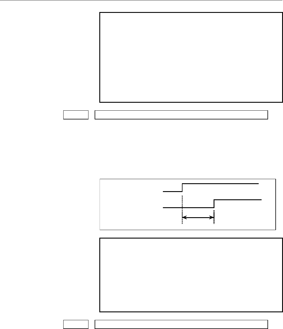
The time required to send strobe signals MF, SF, TF, and BF after the
M, S, T, and B codes are sent, respectively.
M, S, T, B code
MF, SF, TF, BF,
signal
Dela
y
time
NOTE
The time is counted in units of 4 ms. If the set value
is not a multiple of four, it is raised to the next
multiple of four
Example
When 30 is set, 32 ms is assumed.
When 0 is set, 4 ms is assumed.
The time count period may change, depending on
the system.
3011 Acceptable width of M, S, T, and B function completion signal (FIN)
[Input type] Parameter input
[Data type] Word path
[Unit of data] msec
[Valid data range] 0 to 32767
Set the minimum signal width of the valid M, S, T, and B function
completion signal (FIN).
Contents Summary of 30i/300i/300is-Model A, 31i/310i/310is-Model A and A5, Parameter manual
- Page 1FANUC Series 30*/300*/300*s-MODEL A FANUC Series 31*/310*/310*s-MODEL A5 FANUC Series 31*/310*/310*s-MODEL A FANUC Series 32*/320*/320*s-MODEL A PARAMETER MANUAL B-63950EN/02
- Page 2• No part of this manual may be reproduced in any form. • All specifications and designs are subject to change without notice. The export of this product is subject to the authorization of the government of the country from where the product is exported. In this manual we have tried as much as possi
- Page 3B-63950EN/02 DEFINITION OF WARNING, CAUTION, AND NOTE DEFINITION OF WARNING, CAUTION, AND NOTE This manual includes safety precautions for protecting the user and preventing damage to the machine. Precautions are classified into Warning and Caution according to their bearing on safety. Also, supplem
- Page 4
- Page 5B-63950EN/02 PREFACE PREFACE Applicable models The models covered by this manual, and their abbreviations are : Model name Abbreviation FANUC Series 30i-MODEL A 30i –A Series 30i FANUC Series 300i-MODEL A 300i–A Series 300i FANUC Series 300is-MODEL A 300is–A Series 300is FANUC Series 31i-MODEL A 31i
- Page 6PREFACE B-63950EN/02 Related manuals of Series 30i/300i/300is- MODEL A Series 31i/310i/310is- MODEL A Series 31i/310i/310is- MODEL A5 Series 32i/320i/320is- MODEL A The following table lists the manuals related to Series 30i/300i /300is-A, Series 31i/310i /310is-A, Series 31i/310i /310is-A5, Series
- Page 7B-63950EN/02 PREFACE Related manuals of SERVO MOTOR αis/αi series The following table lists the manuals related to SERVO MOTOR αis/αi series Table 2 Related manuals Specification Manual name number FANUC AC SERVO MOTOR αis series FANUC AC SERVO MOTOR αi series B-65262EN DESCRIPTIONS FANUC AC SERVO M
- Page 8
- Page 9B-63950EN/02 TABLE OF CONTENTS TABLE OF CONTENTS DEFINITION OF WARNING, CAUTION, AND NOTE .................................s-1 PREFACE ....................................................................................................p-1 1 DISPLAYING PARAMETERS......................................
- Page 10TABLE OF CONTENTS B-63950EN/02 4.4 PARAMETERS OF SETTING...................................................................... 25 4.5 PARAMETERS OF READER/PUNCHER INTERFACE .............................. 28 4.5.1 Parameters Common to all Channels......................................................
- Page 11B-63950EN/02 TABLE OF CONTENTS 4.33 PARAMETERS OF SKIP FUNCTION ....................................................... 317 4.34 PARAMETERS OF EXTERNAL DATA INPUT/OUTPUT .......................... 329 4.35 PARAMETERS OF FINE TORQUE SENSING.......................................... 331 4.36 PARAMETER
- Page 12TABLE OF CONTENTS B-63950EN/02 4.64 PARAMETERS OF PMC ........................................................................... 450 4.65 PARAMETERS OF HIGH-SPEED POSITION SWITCH (2 OF 2) ............. 457 4.66 PARAMETERS OF MALFUNCTION PROTECTION................................. 459 4.67 PARAMETER
- Page 13B-63950EN/02 1.DISPLAYING PARAMETERS 1 DISPLAYING PARAMETERS Follow the procedure below to display parameters. 1 Press the SYSTEM function key on the MDI as many times as required, or alternatively, press the SYSTEM function key once, then the PARAM section display soft key. The parameter screen is
- Page 142.SETTING PARAMETERS FROM MDI B-63950EN/02 2 SETTING PARAMETERS FROM MDI Follow the procedure below to set parameters. 1 Place the NC in the MDI mode or the emergency stop state. 2 Follow the substeps below to enable writing of parameters. 2-1 To display the setting screen, press the OFFSET SETTING
- Page 15B-63950EN/02 2.SETTING PARAMETERS FROM MDI [Example] 12000 [INPUT] Data can be entered continuously for parameters, starting at the selected parameter, by separating each data item with a semicolon (;). [Example] Entering 10;20;30;40 and pressing the INPUT key assigns values 10, 20, 30, and 40 to pa
- Page 163.INPUTTING AND OUTPUTTING PARAMETERS THROUGH THE READER/PUNCHER INTERFACE B-63950EN/02 3 INPUTTING AND OUTPUTTING PARAMETERS THROUGH THE READER/PUNCHER INTERFACE This section explains the parameter input/output procedures for input/output devices connected to the reader/puncher interface. The follo
- Page 17B-63950EN/02 3.INPUTTING AND OUTPUTTING PARAMETERS THROUGH THE READER/PUNCHER INTERFACE 3.1 OUTPUTTING PARAMETERS THROUGH THE READER/PUNCHER INTERFACE 1 Select the EDIT mode or set to Emergency stop. 2 To select the parameter screen, press the SYSTEM function key as many times as required, or altern
- Page 183.INPUTTING AND OUTPUTTING PARAMETERS THROUGH THE READER/PUNCHER INTERFACE B-63950EN/02 3.2 INPUTTING PARAMETERS THROUGH THE READER/PUNCHER INTERFACE 1 Place the NC in the emergency stop state. 2 Enable parameter writing. 2-1 To display the setting screen, press the OFFSET SETTING function key as ma
- Page 19B-63950EN/02 3.INPUTTING AND OUTPUTTING PARAMETERS THROUGH THE READER/PUNCHER INTERFACE 3.3 I/O FORMATS This section describes the I/O formats of parameters. Parameters are classified by data format as follows: Data format Remarks Bit Data of these formats is Bit machine group represented by an 8-di
- Page 203.INPUTTING AND OUTPUTTING PARAMETERS THROUGH THE READER/PUNCHER INTERFACE B-63950EN/02 3.3.2 Inch/Metric Switching For parameters dependent on inch/metric switching such as those for length and feedrate, whether data is inch data or metric data is specified by the input mode in the case of input fr
- Page 21B-63950EN/02 3.INPUTTING AND OUTPUTTING PARAMETERS THROUGH THE READER/PUNCHER INTERFACE 3.3.4 Bit Machine Group Format N ***** Q1 T ** P ******** T ** P ******** ・ ・ ・ ; A numeric value after N represents a parameter number. Q1 indicates that the data is parameter data. A numeric value after T repre
- Page 223.INPUTTING AND OUTPUTTING PARAMETERS THROUGH THE READER/PUNCHER INTERFACE B-63950EN/02 3.3.5 Bit Path Format N ***** Q1 L ** P ******** L ** P ******** ・ ・ ・ ; A numeric value after N represents a parameter number. Q1 indicates that the data is parameter data. A numeric value after L represents a p
- Page 23B-63950EN/02 3.INPUTTING AND OUTPUTTING PARAMETERS THROUGH THE READER/PUNCHER INTERFACE 3.3.6 Binary Axis Format N ***** Q1 A ** P ******** A ** P ******** ・ ・ ・ ; A numeric value after N represents a parameter number. Q1 indicates that the data is parameter data. A numeric value after A represents
- Page 243.INPUTTING AND OUTPUTTING PARAMETERS THROUGH THE READER/PUNCHER INTERFACE B-63950EN/02 3.3.7 Bit Spindle Format N ***** Q1 S ** P ******** S ** P ******** ・ ・ ・ ; A numeric value after N represents a parameter number. Q1 indicates that the data is parameter data. A numeric value after S represents
- Page 25B-63950EN/02 3.INPUTTING AND OUTPUTTING PARAMETERS THROUGH THE READER/PUNCHER INTERFACE 3.3.8 Byte/Word/Two-Word Format N ***** Q1 P ******** ; A numeric value after N represents a parameter number. Q1 indicates that the data is parameter data. A numeric value after P represents a parameter value (i
- Page 263.INPUTTING AND OUTPUTTING PARAMETERS THROUGH THE READER/PUNCHER INTERFACE B-63950EN/02 3.3.10 Byte/Word/Two-Word Path Format N ***** Q1 L ** P ****** L ** P ****** ・ ・ ・ ; A numeric value after N represents a parameter number. Q1 indicates that the data is parameter data. A numeric value after L re
- Page 27B-63950EN/02 3.INPUTTING AND OUTPUTTING PARAMETERS THROUGH THE READER/PUNCHER INTERFACE 3.3.12 Byte/Word/Two-Word Spindle Format N ***** Q1 S ** P ****** S ** P ****** ・ ・ ・ ; A numeric value after N represents a parameter number. Q1 indicates that the data is parameter data. A numeric value after S
- Page 283.INPUTTING AND OUTPUTTING PARAMETERS THROUGH THE READER/PUNCHER INTERFACE B-63950EN/02 3.3.13 Real Number Format N ***** Q1 P ****** ; N ***** Q1 M ****** ; N ***** Q1 I ****** ; A numeric value after N represents a parameter number. Q1 indicates that the data is parameter data. A numeric value aft
- Page 29B-63950EN/02 3.INPUTTING AND OUTPUTTING PARAMETERS THROUGH THE READER/PUNCHER INTERFACE 3.3.15 Real Number Path Format N ***** Q1 L ** P ****** L ** P ****** ・ ・ ・ ; N ***** Q1 L ** M ****** L ** M ****** ・ ・ ・ ; N ***** Q1 L ** I ****** L ** I ****** ・ ・ ・ ; A numeric value after N represents a par
- Page 303.INPUTTING AND OUTPUTTING PARAMETERS THROUGH THE READER/PUNCHER INTERFACE B-63950EN/02 3.3.16 Real Number Axis Format N ***** Q1 A ** P ****** A ** P ****** ・ ・ ・ ; N ***** Q1 A ** M ****** A ** M ****** ・ ・ ・ ; N ***** Q1 A ** I ****** A ** I ****** ・ ・ ・ ; A numeric value after N represents a par
- Page 31B-63950EN/02 3.INPUTTING AND OUTPUTTING PARAMETERS THROUGH THE READER/PUNCHER INTERFACE 3.3.17 Real Number Spindle Format N ***** Q1 S ** P ****** S ** P ****** ・ ・ ・ ; N ***** Q1 S ** M ****** S ** M ****** ・ ・ ・ ; N ***** Q1 S ** I ****** S ** I ****** ・ ・ ・ ; A numeric value after N represents a
- Page 324.DESCRIPTION OF PARAMETERS B-63950EN/02 4 DESCRIPTION OF PARAMETERS 4.1 DATA TYPE Parameters are classified by data type as follows: Data type Valid data range Remarks Bit Bit machine group Bit path 0 or 1 Bit axis Bit spindle Byte Byte machine group Some parameters handle -128 to 127 Byte path the
- Page 33B-63950EN/02 4.DESCRIPTION OF PARAMETERS NOTE 1 Each of the parameters of the bit, bit machine group, bit path, bit axis, and bit spindle types consists of 8 bits for one data number (parameters with eight different meanings). 2 For machine group types, parameters corresponding to the maximum number
- Page 344.DESCRIPTION OF PARAMETERS B-63950EN/02 4.2 REPRESENTATION OF PARAMETERS Parameters of the bit type, bit machine group type, bit path type, bit axis type, and bit spindle type #7 #6 #5 #4 #3 #2 #1 #0 0000 EIA NCR ISP CTV TVC Data No. Data (Data #0 to #7 are bit positions.) Parameters other than the
- Page 35B-63950EN/02 4.DESCRIPTION OF PARAMETERS 4.3 STANDARD PARAMETER SETTING TABLES Overview This section defines the standard minimum data units and valid data ranges of the CNC parameters of the real type, real machine group type, real path type, real axis type, and real spindle type. The data type and
- Page 364.DESCRIPTION OF PARAMETERS B-63950EN/02 (C) Velocity and angular velocity parameters Increment Minimum Unit of data Valid data range system data unit IS-A 0.01 0.0 to +999000.00 IS-B 0.001 0.0 to +999000.000 mm/min IS-C 0.0001 0.0 to +99999.9999 degree/min IS-D 0.00001 0.0 to +9999.99999 IS-E 0.000
- Page 37B-63950EN/02 4.DESCRIPTION OF PARAMETERS 4.4 PARAMETERS OF SETTING #7 #6 #5 #4 #3 #2 #1 #0 0000 SEQ INI ISO TVC [Input type] Setting input [Data type] Bit path #0 TVC TV check 0: Not performed 1: Performed #1 ISO Code used for data output 0: EIA code 1: ISO code NOTE ASCII code is used at all times
- Page 384.DESCRIPTION OF PARAMETERS B-63950EN/02 #7 #6 #5 #4 #3 #2 #1 #0 0001 FCV [Input type] Setting input [Data type] Bit path #1 FCV Program format 0: Series 16 standard format 1: Series 15 format NOTE 1 Programs created in the Series 15 program format can be used for operation on the following function
- Page 39B-63950EN/02 4.DESCRIPTION OF PARAMETERS #7 #6 #5 #4 #3 #2 #1 #0 0010 PEC PRM PZS [Input type] Setting input [Data type] Bit path #0 PZS When a part program is punched out, the O number is: 0: Not zero-suppressed. 1: Zero-suppressed. #1 PRM When parameters are output, the parameters whose values are
- Page 404.DESCRIPTION OF PARAMETERS B-63950EN/02 4.5 PARAMETERS OF READER/PUNCHER INTERFACE To transfer data (programs, parameters, and so forth) to and from an external input/output device through the I/O device interface (RS-232-C serial interface), the parameters described below need to be set. The input
- Page 41B-63950EN/02 4.DESCRIPTION OF PARAMETERS 4.5.1 Parameters Common to all Channels I/O CHANNEL : Input/output device selection, or interface number for a 0020 foreground input device 0021 Foreground output device setting 0022 Background input device setting 0023 Background output device setting [Input
- Page 424.DESCRIPTION OF PARAMETERS B-63950EN/02 Setting of communication with the ladder development tool (FANUC 0024 LADDER-III, ladder editing package) [Input type] Setting input [Data type] Word [Valid data range] 0 to 255 This parameter is used to enable or disable the PMC online connection function. B
- Page 43B-63950EN/02 4.DESCRIPTION OF PARAMETERS #3 NCR Output of the end of block (EOB) in ISO code 0: LF, CR, CR are output. 1: Only LF is output. #6 IOP Stopping a program output or input operation by a reset is: 0: Enabled 1: Disabled (Stopping a program input/output operation with the [STOP] soft key i
- Page 444.DESCRIPTION OF PARAMETERS B-63950EN/02 4.5.2 Parameters of Channel 1 (I/O CHANNEL=0) #7 #6 #5 #4 #3 #2 #1 #0 0101 NFD ASI SB2 [Input type] Parameter input [Data type] Bit #0 SB2 The number of stop bits 0: 1 1: 2 #3 ASI Code used at data input 0: EIA or ISO code (automatically distinguished) 1: ASC
- Page 45B-63950EN/02 4.DESCRIPTION OF PARAMETERS 4.5.3 Parameters of Channel 1 (I/O CHANNEL=1) #7 #6 #5 #4 #3 #2 #1 #0 0111 NFD ASI SB2 [Input type] Parameter input [Data type] Bit #0 SB2 The number of stop bits 0: 1 1: 2 #3 ASI Code used at data input 0: EIA or ISO code (automatically distinguished) 1: ASC
- Page 464.DESCRIPTION OF PARAMETERS B-63950EN/02 4.5.4 Parameters of Channel 2 (I/O CHANNEL=2) #7 #6 #5 #4 #3 #2 #1 #0 0121 NFD ASI SB2 [Input type] Parameter input [Data type] Bit #0 SB2 The number of stop bits 0: 1 1: 2 #3 ASI Code used at data input 0: EIA or ISO code (automatically distinguished) 1: ASC
- Page 47B-63950EN/02 4.DESCRIPTION OF PARAMETERS 4.6 PARAMETERS OF POWER MATE CNC #7 #6 #5 #4 #3 #2 #1 #0 0960 PPE PMN MD2 MD1 [Input type] Parameter input [Data type] Bit path #1 MD1 The input/output destination of slave parameters is: 0: Program memory (when MD2 = 0) 1: Memory card (when MD2 = 0) #2 MD2 T
- Page 484.DESCRIPTION OF PARAMETERS B-63950EN/02 4.7 PARAMETERS OFSYSTEM CONFIGURATION 0980 Machine group number to which each path belongs NOTE When this parameter is set, the power must be turned off before operation is continued. [Input type] Parameter input [Data type] Byte path [Valid data range] 1 to
- Page 49B-63950EN/02 4.DESCRIPTION OF PARAMETERS 0983 Path control type of each path NOTE When this parameter is set, the power must be turned off before operation is continued. [Input type] Parameter input [Data type] Byte path [Valid data range] 0 to 1 Set the path control type of each path. The following
- Page 504.DESCRIPTION OF PARAMETERS B-63950EN/02 4.8 PARAMETERS OF AXIS CONTROL/INCREMENT SYSTEM #7 #6 #5 #4 #3 #2 #1 #0 1000 EEA [Input type] Parameter input [Data type] Bit #0 EEA An extended axis name and extended spindle name are: 0: Invalid 1: Valid #7 #6 #5 #4 #3 #2 #1 #0 1001 INM [Input type] Paramet
- Page 51B-63950EN/02 4.DESCRIPTION OF PARAMETERS #4 XIK When LRP, bit 1 of parameter No.1401, is set to 0, namely, when positioning is performed using non-linear type positioning, if an interlock is applied to the machine along one of axes in positioning, 0: The machine stops moving along the axis for which
- Page 524.DESCRIPTION OF PARAMETERS B-63950EN/02 #7 #6 #5 #4 #3 #2 #1 #0 1005 RMBx MCCx EDMx EDPx HJZx DLZx ZRNx [Input type] Parameter input [Data type] Bit axis #0 ZRNx If a move command other than G28 is specified by automatic operation when no reference position return is performed yet after the power i
- Page 53B-63950EN/02 4.DESCRIPTION OF PARAMETERS 1: Valid #6 MCCx If a multi-axis amplifier is used, and another axis of the same amplifier is placed in the control axis detach state, the MCC signal of the servo amplifier is: 0: Turned off. 1: Not turned off. NOTE 1 This parameter can be set for a control a
- Page 544.DESCRIPTION OF PARAMETERS B-63950EN/02 1: Diameter specification #5 ZMIx The direction of manual reference position return is: 0: + direction 1: - direction #7 #6 #5 #4 #3 #2 #1 #0 1007 G90x GRDx RAAx ALZx RTLx [Input type] Parameter input [Data type] Bit axis #0 RTLx When manual reference positio
- Page 55B-63950EN/02 4.DESCRIPTION OF PARAMETERS NOTE RAA is valid when bit 0 (ROA) of parameter No. 1008 is set to 1 and bit 1 (RAB) of parameter No. 1008 is set to 0. To use this function, the option for rotary axis control is required. #4 GRDx For the axis on which absolute values are detected, when corr
- Page 564.DESCRIPTION OF PARAMETERS B-63950EN/02 NOTE 1 RRLx is valid only when ROAx is 1. 2 Assign the amount of the shift per one rotation in parameter No.1260. #4 SFDx In reference position return based on the grid method, the reference position shift function is: 0: Disabled 1: Enabled #5 RMCx When mach
- Page 57B-63950EN/02 4.DESCRIPTION OF PARAMETERS #7 #6 #5 #4 #3 #2 #1 #0 1012 IDGx [Input type] Parameter input [Data type] Bit axis #0 IDGx The function for setting the reference position again, without dogs, is: 0: Not inhibited. 1: Inhibited. (The alarm (PS0301) is issued.) NOTE IDGx is enabled when the
- Page 584.DESCRIPTION OF PARAMETERS B-63950EN/02 #7 #6 #5 #4 #3 #2 #1 #0 1013 ISEx ISDx ISCx ISAx [Input type] Parameter input [Data type] Bit axis NOTE When this parameter is set, the power must be turned off before operation is continued. #0 ISA #1 ISC #2 ISD #3 ISE Increment system of each axis Increment
- Page 59B-63950EN/02 4.DESCRIPTION OF PARAMETERS #7 DWT When time for dwell per second is specified by P, the increment system: 0: Depends on the increment system 1: Does not depend on the increment system (1 ms) 1020 Program axis name for each axis [Input type] Parameter input [Data type] Byte axis [Valid
- Page 604.DESCRIPTION OF PARAMETERS B-63950EN/02 1022 Setting of each axis in the basic coordinate system [Input type] Parameter input [Data type] Byte axis [Valid data range] 0 to 7 To determine a plane for circular interpolation, cutter compensation, and so forth (G17: Xp-Yp plane, G18: Zp-Xp plane, G19:
- Page 61B-63950EN/02 4.DESCRIPTION OF PARAMETERS 1023 Number of the servo axis for each axis NOTE When this parameter is set, the power must be turned off before operation is continued. [Input type] Parameter input [Data type] Byte axis [Valid data range] 0 to Number of controlled axes Set the servo axis fo
- Page 624.DESCRIPTION OF PARAMETERS B-63950EN/02 1031 Reference axis [Input type] Parameter input [Data type] Byte path [Valid data range] 0 to Number of controlled axes The unit of some parameters common to all axes such as those for dry run feedrate and single-digit F1 feedrate may vary according to the i
- Page 63B-63950EN/02 4.DESCRIPTION OF PARAMETERS 4.9 PARAMETERS OF COORDINATES #7 #6 #5 #4 #3 #2 #1 #0 WZR NWS FPC ZCL ZPR 1201 WZR FPC ZCL ZPR [Input type] Parameter input [Data type] Bit path #0 ZPR Automatic setting of a coordinate system when the manual reference position return is performed 0: Not set
- Page 644.DESCRIPTION OF PARAMETERS B-63950EN/02 NOTE When the workpiece coordinate shift amount setting screen is not displayed, a workpiece coordinate system shift amount modification using G10P0 cannot be made. #7 WZR If the CNC is reset by the reset key on the MDI panel, external reset signal, reset and
- Page 65B-63950EN/02 4.DESCRIPTION OF PARAMETERS NOTE When the external workpiece zero point offset is made invalid, the following operation results: 1 As the external workpiece zero point offset on the workpiece zero point offset setting screen, a workpiece coordinate system shift amount is displayed. 2 Da
- Page 664.DESCRIPTION OF PARAMETERS B-63950EN/02 #7 #6 #5 #4 #3 #2 #1 #0 1203 EMS [Input type] Parameter input [Data type] Bit path #0 EMS The extended external machine zero point shift function is: 0: Disabled. 1: Enabled. NOTE 1 To use the extended external machine zero point shift function, the external
- Page 67B-63950EN/02 4.DESCRIPTION OF PARAMETERS 1221 Workpiece zero point offset value in workpiece coordinate system 1 (G54) 1222 Workpiece zero point offset value in workpiece coordinate system 2(G55) 1223 Workpiece zero point offset value in workpiece coordinate system 3(G56) 1224 Workpiece zero point o
- Page 684.DESCRIPTION OF PARAMETERS B-63950EN/02 Coordinate value of the second reference position in the machine coordinate 1241 system Coordinate value of the third reference position in the machine coordinate 1242 system Coordinate value of the fourth reference position in the machine coordinate 1243 sys
- Page 69B-63950EN/02 4.DESCRIPTION OF PARAMETERS 1260 Amount of a shift per one rotation of a rotation axis NOTE When this parameter is set, the power must be turned off before operation is continued. [Input type] Parameter input [Data type] Real axis [Unit of data] Degree [Minimum unit of data] Depend on t
- Page 704.DESCRIPTION OF PARAMETERS B-63950EN/02 4.10 PARAMETERS OF STORED STROKE CHECK #7 #6 #5 #4 #3 #2 #1 #0 1300 BFA RL3 LMS NAL OUT [Input type] Setting input [Data type] Bit path #0 OUT The area inside or outside of the stored stroke check 2 is set as an inhibition area 0: Inside 1: Outside #1 NAL Whe
- Page 71B-63950EN/02 4.DESCRIPTION OF PARAMETERS #7 #6 #5 #4 #3 #2 #1 #0 1301 PLC OTS NPC DLM [Input type] Setting input [Data type] Bit path #0 DLM The stored stroke limit switching signals +EXLx and -EXLx for each axial direction are: 0: Disabled. 1: Enabled. When this parameter is set to 1, the stored st
- Page 724.DESCRIPTION OF PARAMETERS B-63950EN/02 1320 Coordinate value I of stored stroke check 1 in the positive direction on each axis 1321 Coordinate value I of stored stroke check 1 in the negative direction on each axis [Input type] Parameter input [Data type] Real axis [Unit of data] mm, inch, degree
- Page 73B-63950EN/02 4.DESCRIPTION OF PARAMETERS 1324 Coordinate value I of stored stroke check 3 in the positive direction on each axis 1325 Coordinate value I of stored stroke check 3 in the negative direction on each axis [Input type] Setting input [Data type] Real axis [Unit of data] mm, inch, degree (m
- Page 744.DESCRIPTION OF PARAMETERS B-63950EN/02 4.11 PARAMETERS OF THE CHUCK AND TAIL STOCK BARRIER Profile of a chuck 1330 [Input type] Parameter input [Data type] Byte path [Valid data range] 0 to 1 Select a chuck figure. 0 : Chuck which holds a workpiece on the inner surface 1 : Chuck which holds a work
- Page 75B-63950EN/02 4.DESCRIPTION OF PARAMETERS Dimensions of the part of a claw at which a workpiece is held (L1) 1333 [Input type] Parameter input [Data type] Real path [Unit of data] mm, inch (input unit) [Minimum unit of data] Depend on the increment system of the applied axis [Valid data range] 0 or p
- Page 764.DESCRIPTION OF PARAMETERS B-63950EN/02 NOTE Whether to specify this parameter by using a diameter value or radius value depends on whether the corresponding axis is based on diameter specification or radius specification. Z coordinate of a chuck (CZ) 1336 [Input type] Parameter input [Data type] R
- Page 77B-63950EN/02 4.DESCRIPTION OF PARAMETERS Diameter of a tail stock (D) 1342 [Input type] Parameter input [Data type] Real path [Unit of data] mm, inch (input unit) [Minimum unit of data] Depend on the increment system of the applied axis [Valid data range] 0 or positive 9 digit of minimum unit of dat
- Page 784.DESCRIPTION OF PARAMETERS B-63950EN/02 Length of a tail stock (L2) 1345 [Input type] Parameter input [Data type] Real path [Unit of data] mm, inch (input unit) [Minimum unit of data] Depend on the increment system of the applied axis [Valid data range] 0 or positive 9 digit of minimum unit of data
- Page 79B-63950EN/02 4.DESCRIPTION OF PARAMETERS Z coordinate of a tail stock (TZ) 1348 [Input type] Parameter input [Data type] Real path [Unit of data] mm, inch (input unit) [Minimum unit of data] Depend on the increment system of the applied axis [Valid data range] 9 digit of minimum unit of data (refer
- Page 804.DESCRIPTION OF PARAMETERS B-63950EN/02 4.12 PARAMETERS OF FEEDRATE #7 #6 #5 #4 #3 #2 #1 #0 1401 RDR TDR RF0 JZR LRP RPD [Input type] Parameter input [Data type] Bit path #0 RPD Manual rapid traverse during the period from power-on time to the completion of the reference position return. 0: Disable
- Page 81B-63950EN/02 4.DESCRIPTION OF PARAMETERS #1 JOV Jog override is: 0: Enabled 1: Disabled (tied to 100%) #3 OV2 Signals used for 2nd feedrate override are 0: *AFV0 to AFV7
(specified every 1%) 1: *APF00 to *APF15 - Page 824.DESCRIPTION OF PARAMETERS B-63950EN/02 #7 #6 #5 #4 #3 #2 #1 #0 FM3 DLF 1404 DLF [Input type] Parameter input [Data type] Bit path #1 DLF After a reference position is set, manual reference position return performed at: 0: Rapid traverse rate (parameter No.1420) 1: Manual rapid traverse rate (param
- Page 83B-63950EN/02 4.DESCRIPTION OF PARAMETERS #5 EDR As the external deceleration rate for positioning of linear interpolation type: 0: The external deceleration rate for cutting feed is used. 1: The external deceleration rate for the first axis in rapid traverse is used. Let us use external deceleration
- Page 844.DESCRIPTION OF PARAMETERS B-63950EN/02 1411 Cutting feedrate NOTE When this parameter is set, the power must be turned off before operation is continued. [Input type] Setting input [Data type] Real path [Unit of data] mm/min, inch/min, degree/min (input unit) [Minimum unit of data] Depend on the i
- Page 85B-63950EN/02 4.DESCRIPTION OF PARAMETERS 1423 Feedrate in manual continuous feed (jog feed) for each axis [Input type] Parameter input [Data type] Real axis [Unit of data] mm/min, inch/min, degree/min (machine unit) [Minimum unit of data] Depend on the increment system of the applied axis [Valid dat
- Page 864.DESCRIPTION OF PARAMETERS B-63950EN/02 1426 External deceleration rate of cutting feed [Input type] Parameter input [Data type] Real path [Unit of data] mm/min, inch/min, degree/min (machine unit) [Minimum unit of data] Depend on the increment system of the reference axis [Valid data range] Refer
- Page 87B-63950EN/02 4.DESCRIPTION OF PARAMETERS NOTE 1 To this feedrate setting (100%), a rapid traverse override (F0, 25, 50, or 100%) is applicable. 2 For automatic return after completion of reference position return and machine coordinate system establishment, the normal rapid traverse rate is used. 3
- Page 884.DESCRIPTION OF PARAMETERS B-63950EN/02 1430 Maximum cutting feedrate for each axis [Input type] Parameter input [Data type] Real axis [Unit of data] mm/min, inch/min, degree/min (machine unit) [Minimum unit of data] Depend on the increment system of the applied axis [Valid data range] Refer to the
- Page 89B-63950EN/02 4.DESCRIPTION OF PARAMETERS 1441 External deceleration rate setting 2 for each axis in rapid traverse [Input type] Parameter input [Data type] Real axis [Unit of data] mm/min, inch/min, degree/min (machine unit) [Minimum unit of data] Depend on the increment system of the applied axis [
- Page 904.DESCRIPTION OF PARAMETERS B-63950EN/02 1466 Feedrate for retraction in threading cycle G92 or G76 [Input type] Parameter input [Data type] Real path [Unit of data] mm/min, inch/min (machine unit) [Minimum unit of data] Depend on the increment system of the reference axis [Valid data range] Refer t
- Page 91B-63950EN/02 4.DESCRIPTION OF PARAMETERS 4.13 PARAMETERS OF ACCELERATION/DECELERATION CONTROL #7 #6 #5 #4 #3 #2 #1 #0 1601 NCI RTO [Input type] Parameter input [Data type] Bit path #4 RTO Block overlap in rapid traverse 0: Blocks are not overlapped in rapid traverse. 1: Blocks are overlapped in rapi
- Page 924.DESCRIPTION OF PARAMETERS B-63950EN/02 #7 #6 #5 #4 #3 #2 #1 #0 1604 SHP [Input type] Parameter input [Data type] Bit path #0 SHP When automatic operation is started, the state equivalent to the specification of G5.1Q1 for AI contour control is: 0: Not set 1: Set Upon reset, the state where G5.1Q1
- Page 93B-63950EN/02 4.DESCRIPTION OF PARAMETERS #7 #6 #5 #4 #3 #2 #1 #0 CFR 1611 [Input type] Parameter input [Data type] Bit path #0 CFR For retraction after threading in the threading cycles G92 and G76: 0: The type of acceleration/deceleration after interpolation for threading is used together with the
- Page 944.DESCRIPTION OF PARAMETERS B-63950EN/02 For bell-shaped acceleration/deceleration Speed Rapid traverse (Parameter No. 1420) T2 T2 T2 T2 Time T1 T1 T1 : Setting of parameter No. 1620 T2 : Setting of parameter No. 1621 (However, T1 ≥ T2 must be satisfied.) Total acceleration (deceleration) time : T1
- Page 95B-63950EN/02 4.DESCRIPTION OF PARAMETERS 1623 FL rate of exponential acceleration/deceleration in cutting feed for each axis [Input type] Parameter input [Data type] Real axis [Unit of data] mm/min, inch/min, degree/min (machine unit) [Minimum unit of data] Depend on the increment system of the appl
- Page 964.DESCRIPTION OF PARAMETERS B-63950EN/02 1627 FL rate for acceleration/deceleration in threading cycles for each axis [Input type] Parameter input [Data type] Real axis [Unit of data] mm/min, inch/min, degree/min (machine unit) [Minimum unit of data] Depend on the increment system of the applied axi
- Page 97B-63950EN/02 4.DESCRIPTION OF PARAMETERS Maximum allowable acceleration rate in acceleration/deceleration before 1671 interpolation for linear rapid traverse for each axis, or maximum allowable reference acceleration rate in optimum torque acceleration/deceleration [Input type] Parameter input [Data
- Page 984.DESCRIPTION OF PARAMETERS B-63950EN/02 Acceleration change time of bell-shaped acceleration/deceleration before interpolation for linear rapid traverse, or acceleration change time of 1672 bell-shaped acceleration/deceleration in optimum torque acceleration/deceleration [Input type] Parameter inpu
- Page 99B-63950EN/02 4.DESCRIPTION OF PARAMETERS Rc Rc:Radius of tool center F× path Rp Rp:Programmed radius Thus, the feedrate along the programmed path satisfies the specified value of F. Programmed path Rc Tool center path Rp However, if Rc is too small when compared with Rp, Rc/Rp 0 results to stop the
- Page 1004.DESCRIPTION OF PARAMETERS B-63950EN/02 1713 Start distance (Le) for inner corner override [Input type] Setting input [Data type] Real path [Unit of data] mm, inch (input unit) [Minimum unit of data] Depend on the increment system of the reference axis [Valid data range] 9 digit of minimum unit of
- Page 101B-63950EN/02 4.DESCRIPTION OF PARAMETERS 1722 Rapid traverse feedrate reduction ratio for overlapping rapid traverse blocks [Input type] Parameter input [Data type] Byte axis [Unit of data] % [Valid data range] 0 to 100 This parameter is used when rapid traverse blocks are arranged successively, or
- Page 1024.DESCRIPTION OF PARAMETERS B-63950EN/02 Maximum allowable acceleration rate for the deceleration function based on 1735 acceleration in circular interpolation for each axis [Input type] Parameter input [Data type] Real axis [Unit of data] mm/sec/sec, inch/sec/sec, degree/sec/sec (machine unit) [Min
- Page 103B-63950EN/02 4.DESCRIPTION OF PARAMETERS Minimum allowable feedrate for the deceleration function based on 1738 acceleration in AI contour control [Input type] Parameter input [Data type] Real path [Unit of data] mm/min, inch/min, degree/min (machine unit) [Minimum unit of data] Depend on the increm
- Page 1044.DESCRIPTION OF PARAMETERS B-63950EN/02 Acceleration change time of bell-shaped acceleration/deceleration before 1772 interpolation [Input type] Parameter input [Data type] 2-word path [Unit of data] msec [Valid data range] 0 to 200 Set an acceleration change time of bell-shaped acceleration/ decel
- Page 105B-63950EN/02 4.DESCRIPTION OF PARAMETERS Maximum allowable acceleration change rate in feedrate determination 1788 based on acceleration change for each axis [Input type] Parameter input [Data type] Real axis [Unit of data] mm/sec/sec, inch/sec/sec, degree/sec/sec (machine unit) [Minimum unit of dat
- Page 1064.DESCRIPTION OF PARAMETERS B-63950EN/02 Ratio of change time of the rate of change of acceleration in smooth 1790 bell-shaped acceleration/deceleration before interpolation [Input type] Parameter input [Data type] Byte path [Unit of data] % [Valid data range] 0 to 50 Set the ratio of the change tim
- Page 107B-63950EN/02 4.DESCRIPTION OF PARAMETERS 4.14 PARAMETERS OF SERVO #7 #6 #5 #4 #3 #2 #1 #0 1800 RBK FFR CVR [Input type] Parameter input [Data type] Bit path #1 CVR When velocity control ready signal VRDY is set ON before position control ready signal PRDY comes ON 0: A servo alarm is generated. 1: A
- Page 1084.DESCRIPTION OF PARAMETERS B-63950EN/02 #5 CIN When CCI is set to 1, the dedicated parameter for specifying an in-position width for cutting feed is used: 0: Only when the next block specifies cutting feed. 1: Regardless of the next block. The table below indicates the relationships between the par
- Page 109B-63950EN/02 4.DESCRIPTION OF PARAMETERS NOTE 1 When this parameter is set to 1, specify the direction of the scale zero point by setting bit 4 (SCP) of parameter No. 1817. 2 When a rotary encoder with absolute address reference marks is used, this parameter is invalid. Even when this parameter is s
- Page 1104.DESCRIPTION OF PARAMETERS B-63950EN/02 #5 ANA When an abnormal load is detected for an axis: 0: Movement along all axes is stopped, and a servo alarm is output. 1: No servo alarm is output, and movement along only the axes of the group containing the axis with the abnormal load is stopped in inter
- Page 111B-63950EN/02 4.DESCRIPTION OF PARAMETERS [Input type] Parameter input [Data type] Bit axis #7 ALGx The servo axis loop gain in the Cs contour control mode is: 0: Not matched with the Cs contour control loop gain. 1: Matched with the Cs contour control loop gain. #7 #6 #5 #4 #3 #2 #1 #0 1815 RONx APC
- Page 1124.DESCRIPTION OF PARAMETERS B-63950EN/02 position on the absolute position detector, and sets this parameter to 1 automatically. #5 APCx Position detector 0: Other than absolute position detector 1: Absolute position detector (absolute pulse coder) #6 RONx With a rotation axis, a rotary encoder for
- Page 113B-63950EN/02 4.DESCRIPTION OF PARAMETERS #4 SCPx For two-point measurement (when bit 2 (DC2) of parameter No. 1802 is set to 1), the scale zero point direction is: 0: On the minus side. (The reference position is located in the plus direction when viewed from the scale zero point.) 1: On the plus si
- Page 1144.DESCRIPTION OF PARAMETERS B-63950EN/02 1818 SDC DG0 RF2x RFSx [Input type] Parameter input [Data type] Bit axis #0 RFSx If G28 is specified for an axis for which a reference position is not established (ZRF = 0) when a linear scale with an absolute address zero point or a linear scale with absolut
- Page 115B-63950EN/02 4.DESCRIPTION OF PARAMETERS When *FLWU is 0, follow-up is performed. When *FLWU is 1, follow-up is not performed. 1: Follow-up is not performed. NOTE When using the index table indexing function, set FUPx to 1 for a control axis subject to index table indexing. #1 CRFx When the servo al
- Page 1164.DESCRIPTION OF PARAMETERS B-63950EN/02 Relationship between the increment system and the least command increment (1) T series Least command Least input increment increment Millimeter 0.001 mm (diameter specification) 0.0005 mm Millimeter input 0.001 mm (radius specification) 0.001 mm machine 0.000
- Page 117B-63950EN/02 4.DESCRIPTION OF PARAMETERS Least command Least input increment increment Millimeter 0.0001 mm (diameter specification) 0.00005 mm Millimeter input 0.0001 mm (radius specification) 0.0001 mm machine 0.00001 inch (diameter specification) 0.00005 mm Inch input 0.00001 inch (radius specifi
- Page 1184.DESCRIPTION OF PARAMETERS B-63950EN/02 Command pulse + DA To ×CMR Error counter least Converter velocity command - control increment Position Reference counter ×DMR detector Detection Feedback unit pulse Set CMR and DMR so that the pulse weight of + input (command from the CNC) into the error coun
- Page 119B-63950EN/02 4.DESCRIPTION OF PARAMETERS 1821 Reference counter size for each axis NOTE When this parameter is set, the power must be turned off before operation is continued. [Input type] Parameter input [Data type] 2-word axis [Unit of data] Detection unit [Valid data range] 0 to 999999999 Set a r
- Page 1204.DESCRIPTION OF PARAMETERS B-63950EN/02 1825 Servo loop gain for each axis [Input type] Parameter input [Data type] Word axis [Unit of data] 0.01/sec [Valid data range] 1 to 9999 Set the loop gain for position control for each axis. When the machine performs linear and circular interpolation (cutti
- Page 121B-63950EN/02 4.DESCRIPTION OF PARAMETERS 1828 Positioning deviation limit for each axis in movement [Input type] Parameter input [Data type] 2-word axis [Unit of data] Detection unit [Valid data range] 0 to 99999999 Set the positioning deviation limit in movement for each axis. If the positioning de
- Page 1224.DESCRIPTION OF PARAMETERS B-63950EN/02 1832 Feed stop positioning deviation for each axis [Input type] Parameter input [Data type] 2-word axis [Unit of data] Detection unit [Valid data range] 0 to 99999999 Set the feed stop positioning deviation for each axis. If the positioning deviation exceeds
- Page 123B-63950EN/02 4.DESCRIPTION OF PARAMETERS Distance to the first grid point after the deceleration dog is turned off in the 1844 case where the reference position shift amount of the reference position shift function is 0 NOTE When this parameter is set, the power must be turned off before operation i
- Page 1244.DESCRIPTION OF PARAMETERS B-63950EN/02 1848 Value of the first stage of smooth backlash compensation [Input type] Parameter input [Data type] Word axis [Unit of data] Detection unit [Valid data range] -9999 to 9999 Set the value of the first stage of smooth backlash compensation for each axis. 185
- Page 125B-63950EN/02 4.DESCRIPTION OF PARAMETERS 1852 Backlash compensating value used for rapid traverse for each axis [Input type] Parameter input [Data type] Word axis [Unit of data] Detection unit [Valid data range] -9999 to 9999 Set the backlash compensating value used in rapid traverse for each axis.
- Page 1264.DESCRIPTION OF PARAMETERS B-63950EN/02 1880 Abnormal load detection alarm timer [Input type] Parameter input [Data type] Word path [Unit of data] msec [Valid data range] 0 to 32767 This parameter sets the time from the detection of an abnormal load until a servo alarm is issued. When 0 is set, how
- Page 127B-63950EN/02 4.DESCRIPTION OF PARAMETERS 1883 Distance 1 from the scale zero point to reference position NOTE When this parameter is set, the power must be turned off before operation is continued. [Input type] Parameter input [Data type] 2-word axis [Unit of data] Detection unit [Valid data range]
- Page 1284.DESCRIPTION OF PARAMETERS B-63950EN/02 Reference position Zero point of encoder Encoder end Mark 1 Mark 2 Mark 1 Mark 2 Mark 1 = mark 2 …….. 8.0 42.0 8.2 41.8 PRM.1821 PRM.1882 PRM.1884 × 100,000,000 + PRM.1883 [Example of parameter settings] When an encoder as shown below is used with an IS-B, mi
- Page 129B-63950EN/02 4.DESCRIPTION OF PARAMETERS (As a result, the machine coordinate represents the distance from the scale zero point to the current position.) <3> By jog feed or handle feed, place the machine at the accurate reference position. <4> In parameter No. 1883, set the machine coordinate of tha
- Page 1304.DESCRIPTION OF PARAMETERS B-63950EN/02 #7 #6 #5 #4 #3 #2 #1 #0 1902 ASE FMD [Input type] Parameter input [Data type] Bit NOTE When this parameter is set, the power must be turned off before operation is continued. #0 FMD The FSSB setting mode is: 0: Automatic setting mode. (When the relationship b
- Page 131B-63950EN/02 4.DESCRIPTION OF PARAMETERS #7 PM2 The second separate detector interface unit is: 0: Not used. 1: Used. NOTE When automatic setting mode is selected for FSSB setting (when the parameter FMD (No.1902#0) is set to 0), this parameter is automatically set when input is performed with the F
- Page 1324.DESCRIPTION OF PARAMETERS B-63950EN/02 Example of setting) Separate detector connection destination Parameter setting Controlled Connectors Connectors Connectors Connectors No. No. No. No. No.1905 axis for 1st unit for 2nd unit for 3rd unit for 4th unit 1936 1937 1938 1939 (#7,#6,#2,#1) X1 JF101 -
- Page 133B-63950EN/02 4.DESCRIPTION OF PARAMETERS Parameters No.2000 to 2999 are for digital servo, The following parameters are not explained in this manual. Refer to FANUC AC SERVO MOTOR αi series PARAMETER MANUAL (B-65270EN) No. Data type Contents 2000 Bit axis PGEX PRMC DGPR PLC0 2001 Bit axis AMR7 AMR6
- Page 1344.DESCRIPTION OF PARAMETERS B-63950EN/02 No. Data type Contents 2057 Word axis Current phase lead compensation (PVPA) 2058 Word axis Current phase lead compensation (PALPH) 2059 Word axis Counterelectromotive force compensation (EMFBAS) 2060 Word axis Torque limit 2061 Word axis Counterelectromotive
- Page 135B-63950EN/02 4.DESCRIPTION OF PARAMETERS No. Data type Contents 2122 Word axis Conversion coefficient for detected resistance 2126 Word axis Tandem control , time constant for switching position feedback 2127 Word axis Non-interacting control coefficient 2128 Word axis Weak magnetic flux compensatio
- Page 1364.DESCRIPTION OF PARAMETERS B-63950EN/02 #7 #6 #5 #4 #3 #2 #1 #0 2008 VFA TDM [Input type] Parameter input [Data type] Bit axis #1 TDM This bit is automatically set to 1 when bit 6 (tandem axis) of parameter No. 1817 is set to 1. This bit cannot be directly set. #2 VFA In tandem control, the feedrat
- Page 137B-63950EN/02 4.DESCRIPTION OF PARAMETERS 2087 Preload value for each axis (Tcmd offset) [Input type] Parameter input [Data type] Word axis [Unit of data] (Ampere limit)/7282 [Valid data range] -1821 to 1821 An offset is applied to a torque command to suppress backlash. Set a value much greater than
- Page 1384.DESCRIPTION OF PARAMETERS B-63950EN/02 4.15 PARAMETERS OF DI/DO #7 #6 #5 #4 #3 #2 #1 #0 3001 MHI SON [Input type] Parameter input [Data type] Bit path #1 SON Automatic operation is started: 0: On the falling edge ("1" → "0") of the automatic operation start signal ST 1: On the rising edge ("0" → "
- Page 139B-63950EN/02 4.DESCRIPTION OF PARAMETERS #7 #6 #5 #4 #3 #2 #1 #0 3003 DEC DAU DIT ITX ITL DEC DIT ITX ITL [Input type] Parameter input [Data type] Bit path #0 ITL Interlock signal for all axes 0: Enabled 1: Disabled #2 ITX Interlock signals for each axis 0: Enabled 1: Disabled #3 DIT The interlock s
- Page 1404.DESCRIPTION OF PARAMETERS B-63950EN/02 For safety, usually set 0 to check the overtravel limit signal. #7 #6 #5 #4 #3 #2 #1 #0 3006 EP2 EPS EPN GDC [Input type] Parameter input [Data type] Bit #0 GDC As the deceleration signal for reference position return: 0: X0009 is used. 1: G0196 is used. (X00
- Page 141B-63950EN/02 4.DESCRIPTION OF PARAMETERS NOTE When this parameter is set to 1, set parameter No. 3013, No. 3014, No. 3012, and No. 3019. If parameter No. 3013 and No. 3014 are not set, the deceleration signal for reference position return is assigned to bit 0 of X0000. If parameter No. 3012 and No.
- Page 1424.DESCRIPTION OF PARAMETERS B-63950EN/02 M, S, T, B code MF, SF, TF, BF signal FIN sigal Ignored because shorter Valid because longer than min. signal width than min. signal width NOTE The time is counted in units of 4 ms. If the set value is not a multiple of four, it is raised to the next multiple
- Page 143B-63950EN/02 4.DESCRIPTION OF PARAMETERS X address to which the deceleration signal for reference position return is 3013 assigned NOTE When this parameter is set, the power must be turned off before operation is continued. [Input type] Parameter input [Data type] Word axis [Valid data range] 0 to 7
- Page 1444.DESCRIPTION OF PARAMETERS B-63950EN/02 Address to which the PMC axis control skip signal and the measurement 3019 position arrival signal are assigned NOTE When this parameter is set, the power must be turned off before operation is continued. [Input type] Parameter input [Data type] Word path [Va
- Page 145B-63950EN/02 4.DESCRIPTION OF PARAMETERS Correspondence between workpiece numbers and program numbers in 3020 external workpiece number search (PN) [Input type] Parameter input [Data type] 2-word path [Valid data range] -1 to 999999 This parameter has the following meaning according to the value set
- Page 1464.DESCRIPTION OF PARAMETERS B-63950EN/02 +J1
, -J1 , 1 0 ZP1 , ... +J2 , -J2 , 2 1 ZP2 , ... +J3 , -J3 , 3 2 ZP3 , ... +J4 , -J4 , 4 10 ZP4 , ... +J5 , -J5 , 5 11 ZP5 , ... If eigh - Page 147B-63950EN/02 4.DESCRIPTION OF PARAMETERS number 1 0 TLMLA
, TLMHA , ALMA , ... 2 1 TLMLB , TLMHB , ALMB , ... 3 10 TLMLA , TLMHA , ALMA , ... 4 11 TLMLB , TLMHB , ALMB , ... If four or less axes are used - Page 1484.DESCRIPTION OF PARAMETERS B-63950EN/02 4.16 PARAMETERS OF DISPLAY AND EDIT (1/2) #7 #6 #5 #4 #3 #2 #1 #0 3101 KBF [Input type] Parameter input [Data type] Bit #1 KBF When the screen or mode is changed, the contents of the key-in buffer are: 0: Cleared. 1: Not cleared. #7 #6 #5 #4 #3 #2 #1 #0 DAC P
- Page 149B-63950EN/02 4.DESCRIPTION OF PARAMETERS #4 DRL Relative position 0: The actual position displayed takes into account tool length offset. 1: The programmed position displayed does not take into account tool length offset. #6 DAL Absolute position 0: The actual position displayed takes into account t
- Page 1504.DESCRIPTION OF PARAMETERS B-63950EN/02 #6 DAK When absolute coordinates are displayed in the three-dimensional coordinate conversion mode: 0: Coordinates in the program coordinate system are displayed. 1: Coordinates in the workpiece coordinate system are displayed. #7 #6 #5 #4 #3 #2 #1 #0 3108 JS
- Page 151B-63950EN/02 4.DESCRIPTION OF PARAMETERS 1: Not displayed. #7 #6 #5 #4 #3 #2 #1 #0 3111 SVP SPS SVS [Input type] Setting input [Data type] Bit path #0 SVS Servo setting screen and servo tuning screen 0: Not displayed 1: Displayed #1 SPS Spindle tuning screen 0: Not displayed 1: Displayed #2 SVP Spin
- Page 1524.DESCRIPTION OF PARAMETERS B-63950EN/02 operation is performed. Set this parameter to 1 only when performing touch panel compensation. Upon completion of compensation, set this parameter to 0. #7 #6 #5 #4 #3 #2 #1 #0 3114 ICU IGR IMS ISY IOF IPR IPO [Input type] Parameter input [Data type] Bit #0 I
- Page 153B-63950EN/02 4.DESCRIPTION OF PARAMETERS #7 #6 #5 #4 #3 #2 #1 #0 3115 APLx NDFx [Input type] Parameter input [Data type] Bit axis #3 NDFx In calculation for actual cutting feedrate display, the feedrate of a selected axis is: 0: Considered. 1: Not considered. #5 APLx When the active offset value mod
- Page 1544.DESCRIPTION OF PARAMETERS B-63950EN/02 By the setting above, the settings of the existing parameters 100 and 121 through 123 become invalid for channel 2 (JD36B or JD54), and the following settings are applied at all times: - Baud rate : 19200 bps - Stop bit : 1 bit - Parity check : Even parity 31
- Page 155B-63950EN/02 4.DESCRIPTION OF PARAMETERS 3128 Retracement time for deleting alarm data from the alarm history [Input type] Parameter input [Data type] Word path [Unit of data] sec [Valid data range] 0 to 255 From the alarm history, the alarm data that occurred during a set period of time back from t
- Page 1564.DESCRIPTION OF PARAMETERS B-63950EN/02 Example) When the axis name is X, a subscript is added as indicated below. Setting value Axis name displayed on a screen such as the position display screen 0 X 1 X1 77 XM 83 XS If a multi-path system is used, no extended axis name is used within a path, and
- Page 157B-63950EN/02 4.DESCRIPTION OF PARAMETERS Data display order of each axis on the workpiece coordinate system setting 3134 screen and workpiece coordinate system shift amount setting screen [Input type] Parameter input [Data type] Byte axis [Valid data range] 0 to Number of controlled axes Set the dat
- Page 1584.DESCRIPTION OF PARAMETERS B-63950EN/02 Any character string consisting of alphanumeric characters, katakana characters, and special characters with a maximum length of seven characters can be displayed as a series name. NOTE 1 For characters and codes, see the correspondence table in Appendix A. 2
- Page 159B-63950EN/02 4.DESCRIPTION OF PARAMETERS 1: Displayed. #7 #6 #5 #4 #3 #2 #1 #0 3194 DPM DPA [Input type] Parameter input [Data type] Bit path #2 DPA The absolute coordinates, relative coordinates, and remaining move amount during diameter/radius specification switching are displayed: 0: According to
- Page 1604.DESCRIPTION OF PARAMETERS B-63950EN/02 1: Not completed #6 NPE With an M02, M30, or M99 block, program registration is assumed to be: 0: Completed 1: Not completed #7 #6 #5 #4 #3 #2 #1 #0 3202 PSR NE9 NE8 [Input type] Parameter input [Data type] Bit path #0 NE8 Editing of subprograms with program
- Page 161B-63950EN/02 4.DESCRIPTION OF PARAMETERS [Input type] Parameter input [Data type] Bit path #5 MZE After MDI operation is started, program editing during operation is: 0: Enabled 1: Disabled #6 MER When the last block of a program has been executed at single block operation in the MDI mode, the execu
- Page 1624.DESCRIPTION OF PARAMETERS B-63950EN/02 [Data type] Bit #1 MIF Editing of the maintenance information screen is: 0: Not prohibited. 1: Prohibited. #7 #6 #5 #4 #3 #2 #1 #0 3208 SKY [Input type] Parameter input [Data type] Bit #0 SKY The function key [SYSTEM] on the MDI panel is: 0: Enabled. 1: Disab
- Page 163B-63950EN/02 4.DESCRIPTION OF PARAMETERS When the value set as the password (set in parameter No.3210) is set in this parameter, the locked state is released and the user can now modify the password and the value set in bit 4 (NE9) of parameter No.3202. NOTE The value set in this parameter is not di
- Page 1644.DESCRIPTION OF PARAMETERS B-63950EN/02 When the values above are set, the programs from O7000 to O8499 can be locked. When PMIN = 0, the specification of PMIN = 9000 is assumed. When PMAX = 0, the specification of PMAX = 9999 is assumed. So, when these parameters are set to the defaults, the progr
- Page 165B-63950EN/02 4.DESCRIPTION OF PARAMETERS 3241 Character blinking in the AI contour control I mode (first character) 3242 Character blinking in the AI contour control I mode (second character) 3243 Character blinking in the AI contour control I mode (third character) 3244 Character blinking in the AI
- Page 1664.DESCRIPTION OF PARAMETERS B-63950EN/02 #7 #6 #5 #4 #3 #2 #1 #0 3280 NLC [Input type] Parameter input [Data type] Bit #0 NLC Dynamic display language switching is: 0: Enabled. 1: Disabled. When dynamic display language switching is disabled, the language setting screen is not displayed. In this cas
- Page 167B-63950EN/02 4.DESCRIPTION OF PARAMETERS NOTE When tool offset memory A is selected with the M series, the tool offset set in the parameter WOF is followed even if geometric compensation and wear compensation are not specified with the T series. #1 GOF Setting the tool geometry offset value by MDI k
- Page 1684.DESCRIPTION OF PARAMETERS B-63950EN/02 3291 WPT [Input type] Parameter input [Data type] Bit path #0 WPT The input of the tool wear compensation amount is: 0: Enabled according to memory protection key signal KEY1. 1: Enabled, regardless of the memory protection key signal KEY1. 3294 Start number
- Page 169B-63950EN/02 4.DESCRIPTION OF PARAMETERS : 3336 Screen number assigned to the 16th vertical soft key [Input type] Parameter input [Data type] Word [Valid data range] 1 to 10000 Assign a screen number to be displayed as a shortcut to a vertical soft key. The 1st to 8th vertical soft keys are displaye
- Page 1704.DESCRIPTION OF PARAMETERS B-63950EN/02 (1) CNC operation screens Screen No. Screen name Screen No. Screen name 99 Display of next page(*1) 143 Spindle setting 100 Absolute position display(*2) 144 Spindle adjustment 101 Relative position display(*2) 145 Spindle monitor 102 Overall position display
- Page 171B-63950EN/02 4.DESCRIPTION OF PARAMETERS (2) PMC operation screens (3) Communication operation screens Screen No. Screen name Screen No. Screen name 200 PMC signal status Ethernet setting 201 PMC IO link 300 [Built-in port] Common 202 PMC alarm 301 [Built-in port] FOCAS2/Ethernet 203 PMC input/outpu
- Page 1724.DESCRIPTION OF PARAMETERS B-63950EN/02 4.17 PARAMETERS OF PROGRAMS #7 #6 #5 #4 #3 #2 #1 #0 3400 SMX PGD MGC MGO [Input type] Parameter input [Data type] Bit path #0 MGO If the program restart M/S/T/B code output function is used: 0: When bit 6 (MOA) of parameter No. 7300 is set to 0, the last M co
- Page 173B-63950EN/02 4.DESCRIPTION OF PARAMETERS #7 #6 #5 #4 #3 #2 #1 #0 GSC GSB DPI 3401 DPI [Input type] Parameter input [Data type] Bit path #0 DPI When a decimal point is omitted in an address that can include a decimal point 0: The least input increment is assumed. (Normal decimal point input) 1: The u
- Page 1744.DESCRIPTION OF PARAMETERS B-63950EN/02 #3 G91 When the power is turned on or when the control is cleared 0: G90 mode (absolute command) 1: G91 mode (incremental command) #4 FPM At power-on time or in the cleared state: 0: G99 or G95 mode (feed per revolution) is set. 1: G98 or G94 mode (feed per m
- Page 175B-63950EN/02 4.DESCRIPTION OF PARAMETERS #4 M30 When M30 is specified in a memory operation: 0: M30 is sent to the machine, and the head of the program is automatically searched for. So, when the ready signal FIN is returned and a reset or reset and rewind operation is not performed, the program is
- Page 1764.DESCRIPTION OF PARAMETERS B-63950EN/02 #7 #6 #5 #4 #3 #2 #1 #0 DDP CCR G36 DWL AUX 3405 DWL AUX [Input type] Parameter input [Data type] Bit path #0 AUX When the second auxiliary function is specified in the calculator-type decimal point input format or with a decimal point, the multiplication fac
- Page 177B-63950EN/02 4.DESCRIPTION OF PARAMETERS #4 CCR Addresses used for chamfering 0: Address is “I”, “J”, or “K”. In direct drawing dimension programming, addresses ",C", ",R", and ",A" (with comma) are used in stead of "C", "R", and "A". 1: Address is “C”. Addresses used for direct drawing dimension pr
- Page 1784.DESCRIPTION OF PARAMETERS B-63950EN/02 Parameter G code group C01 01 C02 02 C03 03 : : D30 30 #7 CFH When parameter CLR (No.3402#6) is 1, the reset button on the MDI panel, the external reset signal, the reset and rewind signal, or emergency stop will, 0: Clear F codes, H codes (for the M series),
- Page 179B-63950EN/02 4.DESCRIPTION OF PARAMETERS 3421 Range specification 1 of M codes that do not perform buffering (lower limit) 3422 Range specification 1 of M codes that do not perform buffering (upper limit) 3423 Range specification 2 of M codes that do not perform buffering (lower limit) 3424 Range sp
- Page 1804.DESCRIPTION OF PARAMETERS B-63950EN/02 Range specification 1 of second auxiliary function codes that do not perform 3436 buffering (lower limit) Range specification 1 of second auxiliary function codes that do not perform 3437 buffering (upper limit) Range specification 2 of second auxiliary funct
- Page 181B-63950EN/02 4.DESCRIPTION OF PARAMETERS #7 #6 #5 #4 #3 #2 #1 #0 3450 BDX AUP [Input type] Parameter input [Data type] Bit path #0 AUP The second auxiliary function specified in the calculator-type decimal point input format, with a decimal point, or with a negative value is: 0: Disabled. 1: Enabled
- Page 1824.DESCRIPTION OF PARAMETERS B-63950EN/02 3451 GQS [Input type] Parameter input [Data type] Bit path #0 GQS When threading is specified, the threading start angle shift function (Q) is: 0: Disabled. 1: Enabled. #7 #6 #5 #4 #3 #2 #1 #0 3452 EAP [Input type] Parameter input [Data type] Bit path #7 EAP
- Page 183B-63950EN/02 4.DESCRIPTION OF PARAMETERS #7 #6 #5 #4 #3 #2 #1 #0 3455 AXDx [Input type] Parameter input [Data type] Bit axis #0 AXDx If a decimal point is omitted for an axis address with which a decimal point can be used, the value is determined: 0: In accordance with the least input increment. (No
- Page 1844.DESCRIPTION OF PARAMETERS B-63950EN/02 1: Not set as a search directory. #1 MC2 MTB dedicated directory 2 "//CNC_MEM/MTB2/" of the initial directories is: 0: Set as a search directory. 1: Not set as a search directory. #2 MC1 MTB dedicated directory 1 "//CNC_MEM/MTB1/" of the initial directories i
- Page 185B-63950EN/02 4.DESCRIPTION OF PARAMETERS interpolation or conic interpolation [Input type] Parameter input [Data type] Real axis [Unit of data] mm, inch (input unit) [Minimum unit of data] Depend on the increment system of the applied axis [Valid data range] 0 to 999999999 This parameter sets the ma
- Page 1864.DESCRIPTION OF PARAMETERS B-63950EN/02 4.18 PARAMETERS OF PITCH ERROR COMPENSATION #7 #6 #5 #4 #3 #2 #1 #0 3601 EPC [Input type] Parameter input [Data type] Bit path NOTE When this parameter is set, the power must be turned off before operation is continued. #1 EPC The pitch error compensation on
- Page 187B-63950EN/02 4.DESCRIPTION OF PARAMETERS When the maximum feedrate is 15000 mm/min, and the maximum pitch error compensation value is 7 pulses, the minimum compensation point interval is 16mm. NOTE Interpolation type pitch error compensation cannot be used with spindle positioning. Number of the pit
- Page 1884.DESCRIPTION OF PARAMETERS B-63950EN/02 NOTE When this parameter is set, the power must be turned off before operation is continued. [Input type] Parameter input [Data type] Byte axis [Valid data range] 0 to 100 Set the magnification for pitch error compensation for each axis. If the magnification
- Page 189B-63950EN/02 4.DESCRIPTION OF PARAMETERS Travel distance per revolution in pitch error compensation of rotation axis 3625 type NOTE When this parameter is set, the power must be turned off before operation is continued. [Input type] Parameter input [Data type] Real axis [Unit of data] mm, inch, degr
- Page 1904.DESCRIPTION OF PARAMETERS B-63950EN/02 NOTE 1 For a movement in the positive direction, set the compensation point number at the farthest end in the negative direction in parameter No. 3621. 2 A set of compensation data items for a single axis should not be set to lie astride 1023 to 3000. Pitch e
- Page 191B-63950EN/02 4.DESCRIPTION OF PARAMETERS Number of the pitch error compensation position at extremely negative 3666 position for each slave axis when independent pitch error compensation is performed under simple spindle synchronous control NOTE When this parameter is set, the power must be turned o
- Page 1924.DESCRIPTION OF PARAMETERS B-63950EN/02 Number of the pitch error compensation position at extremely positive 3671 position for each slave axis when independent pitch error compensation is performed under simple spindle synchronous control NOTE When this parameter is set, the power must be turned o
- Page 193B-63950EN/02 4.DESCRIPTION OF PARAMETERS Number of the pitch error compensation position at extremely negative 3676 position for each slave axis when independent both-direction pitch error compensation is performed under simple spindle synchronous control NOTE When this parameter is set, the power m
- Page 1944.DESCRIPTION OF PARAMETERS B-63950EN/02 Pitch error compensation value at the reference position when a movement is made to the reference position in the direction opposite to the reference 3681 position return direction for each slave axis in the case where independent both-direction pitch error c
- Page 195B-63950EN/02 4.DESCRIPTION OF PARAMETERS 4.19 PARAMETERS OF SPINDLE CONTROL #7 #6 #5 #4 #3 #2 #1 #0 3700 NRF CRF [Input type] Parameter input [Data type] Bit path #0 CRF Reference position setting at an arbitrary position under Cs contour control is: 0: Not used. 1: Used. NOTE When this function is
- Page 1964.DESCRIPTION OF PARAMETERS B-63950EN/02 #7 #6 #5 #4 #3 #2 #1 #0 3703 MPP MPM 2P2 [Input type] Parameter input [Data type] Bit NOTE When this parameter is set, the power must be turned off before operation is continued. #0 2P2 When a multi-path system is used, inter-path spindle control allows: 0: C
- Page 197B-63950EN/02 4.DESCRIPTION OF PARAMETERS #7 #6 #5 #4 #3 #2 #1 #0 3704 CSS SSY SSS [Input type] Parameter input [Data type] Bit path NOTE When this parameter is set, the power must be turned off before operation is continued. #4 SSS Synchronous spindle control by each spindle is: 0: Not performed. 1:
- Page 1984.DESCRIPTION OF PARAMETERS B-63950EN/02 #7 #6 #5 #4 #3 #2 #1 #0 SFA EVS SGT SGB ESF 3705 SFA NSF SGT SGB GST ESF [Input type] Parameter input [Data type] Bit path #0 ESF When the spindle control function (Spindle analog output or Spindle serial output) is used, and the constant surface speed contro
- Page 199B-63950EN/02 4.DESCRIPTION OF PARAMETERS #4 EVS When the spindle control function (Spindle analog output or Spindle serial output) is used, S codes and SF are: 0: Not output for an S command. 1: Output for an S command. The output of S codes and SF for an S command in constant surface speed control
- Page 2004.DESCRIPTION OF PARAMETERS B-63950EN/02 #3 PCS When a multi-path system is used, and multi-spindle control is enabled with each path, as the position coder signals (PC2SLC
, PC3SLC , PC4SLC ) for selecting the position coder of a spindle among the multiple spindles that b - Page 201B-63950EN/02 4.DESCRIPTION OF PARAMETERS NOTE 1 M type The gear selection signal is not input. The CNC selects a gear based on the speed range of each gear set by a parameter beforehand according to S codes, and the selected gear is posted by outputting the gear selection signal. Moreover, the spind
- Page 2024.DESCRIPTION OF PARAMETERS B-63950EN/02 #1 SAT Check of the spindle speed arrival signal at the start of executing the thread cutting block 0: The signal is checked only when SAR, #0 of parameter 3708, is set. 1: The signal is always checked irrespective of whether SAR is set. NOTE When thread cutt
- Page 203B-63950EN/02 4.DESCRIPTION OF PARAMETERS 1: For each spindle irrespective of whether the spindle is selected (Each spindle has its own SIND signal). (TYPE-B) #3 MRS When the actual spindle speed signals and S 12-bit code signals are output in multi-spindle control: 0: The signals common to the first
- Page 2044.DESCRIPTION OF PARAMETERS B-63950EN/02 #7 #6 #5 #4 #3 #2 #1 #0 3716 A/Ss [Input type] Parameter input [Data type] Bit spindle NOTE When this parameter is set, the power must be turned off before operation is continued. #0 A/Ss Spindle motor type is : 0: Analog spindle. (Prohibition of use) 1: Seri
- Page 205B-63950EN/02 4.DESCRIPTION OF PARAMETERS 3719 Subscript for display of a serial spindle (sub-spindle) [Input type] Parameter input [Data type] Byte spindle [Valid data range] 0 to 122 Set a subscript to be added to spindle speed display on a screen such as the position display screen. 3720 Number of
- Page 2064.DESCRIPTION OF PARAMETERS B-63950EN/02 3730 Data used for adjusting the gain of the analog output of spindle speed [Input type] Parameter input [Data type] Word spindle [Unit of data] 0.1% [Valid data range] 700 to 1250 Set data used for adjusting the gain of the analog output of spindle speed. [A
- Page 207B-63950EN/02 4.DESCRIPTION OF PARAMETERS The spindle speed during spindle orientation or the spindle motor speed 3732 during spindle gear shift [Input type] Parameter input [Data type] 2-word path [Valid data range] 0 to 20000 Set the spindle speed during spindle orientation or the spindle motor spe
- Page 2084.DESCRIPTION OF PARAMETERS B-63950EN/02 3735 Minimum clamp speed of the spindle motor [Input type] Parameter input [Data type] Word path [Valid data range] 0 to 4095 Set the minimum clamp speed of the spindle motor. Setting value = (Minimum clamp speed of the spindle motor / Maximum spindle motor s
- Page 209B-63950EN/02 4.DESCRIPTION OF PARAMETERS 3738 Spindle name 2 of each spindle 3739 Spindle name 3 of each spindle [Input type] Parameter input [Data type] Byte spindle [Valid data range] 48to57,65to90 The command for a spindle is basically "S". When all conditions below are satisfied, however, an ext
- Page 2104.DESCRIPTION OF PARAMETERS B-63950EN/02 3741 Maximum spindle speed for gear 1 3742 Maximum spindle speed for gear 2 3743 Maximum spindle speed for gear 3 3744 Maximum spindle speed for gear 4 [Input type] Parameter input [Data type] 2-word spindle [Unit of data] min-1 [Valid data range] 0 to 999999
- Page 211B-63950EN/02 4.DESCRIPTION OF PARAMETERS 3751 Spindle motor speed when switching from gear 1 to gear 2 3752 Spindle motor speed when switching from gear 2 to gear 3 [Input type] Parameter input [Data type] Word path [Valid data range] 0 to 4095 For gear switching method B, set the spindle motor spee
- Page 2124.DESCRIPTION OF PARAMETERS B-63950EN/02 3761 Spindle speed when switching from gear 1 to gear 2 during tapping 3762 Spindle speed when switching from gear 2 to gear 3 during tapping [Input type] Parameter input [Data type] 2-word path [Unit of data] min-1 [Valid data range] 0 to 99999999 When metho
- Page 213B-63950EN/02 4.DESCRIPTION OF PARAMETERS 3770 Axis as the calculation reference in constant surface speed control [Input type] Parameter input [Data type] Byte path [Valid data range] 0 to Number of controlled axes Set the axis as the calculation reference in constant surface speed control. NOTE Whe
- Page 2144.DESCRIPTION OF PARAMETERS B-63950EN/02 NOTE 1 For M series, this parameter is valid if the function of constant surface speed control is provided. 2 When the constant surface speed control option is selected, the spindle speed is clamped at the maximum speed, regardless of whether the G96 mode or
- Page 215B-63950EN/02 4.DESCRIPTION OF PARAMETERS NOTE 4 Identical P code values cannot be used for different spindles. (Identical P code values cannot be used even if the paths are different.) 5 When this parameter is used (when bit 3 (MPP) of parameter No. 3703 is set to 1), the spindle command selection s
- Page 2164.DESCRIPTION OF PARAMETERS B-63950EN/02 #7 #6 #5 #4 #3 #2 #1 #0 3799 SVPs ASDs NDPs NALs [Input type] Parameter input [Data type] Bit spindle #0 NALs An alarm detected on the spindle amplifier side is: 0: Displayed. 1: Not displayed. (This parameter is valid when bit 0 (ALM) of parameter No. 3798 i
- Page 217B-63950EN/02 4.DESCRIPTION OF PARAMETERS Parameters for Control of Serial Interface Spindle Cs Contouring Control Axis Number Data format Description 3910 Byte path Number of the servo axis whose loop gain is to be changed according to the set values of parameters 3911 to 3914 when the Cs contouring
- Page 2184.DESCRIPTION OF PARAMETERS B-63950EN/02 When there are servo axes for interpolation with the Cs contouring axis, the parameters must be set according to the procedure below for each axis. (1) Set the number of a servo axis (1 to maximum number of controlled axes) for interpolation with the Cs conto
- Page 219B-63950EN/02 4.DESCRIPTION OF PARAMETERS Parameters for Serial interface spindle or spindle Parameters Nos. 4000 to 4539 below are basically used with the serial spindle amplifier (SPM). For details of these parameters, refer to either of the following manuals and other related documents, depending
- Page 2204.DESCRIPTION OF PARAMETERS B-63950EN/02 4196 to to 4309 [Input type] Parameter input [Data type] Word spindle 4310 4311 [Input type] Parameter input [Data type] 2-word spindle 4312 to to 4351 [Input type] Parameter input [Data type] Word spindle #7 #6 #5 #4 #3 #2 #1 #0 4352 4353 [Input type] Parame
- Page 221B-63950EN/02 4.DESCRIPTION OF PARAMETERS #7 #6 #5 #4 #3 #2 #1 #0 4394 to to 4403 [Input type] Parameter input [Data type] Bit spindle 4404 to to 4466 [Input type] Parameter input [Data type] Word spindle #7 #6 #5 #4 #3 #2 #1 #0 4467 to to 4476 [Input type] Parameter input [Data type] Bit spindle 447
- Page 2224.DESCRIPTION OF PARAMETERS B-63950EN/02 NOTE 4 The CNC can control up to eight spindle amplifiers with the serial interface. When the spindle amplifier provides the spindle switching function, one spindle amplifier can control two spindle motors using the switching function. The output switching fu
- Page 223B-63950EN/02 4.DESCRIPTION OF PARAMETERS #7 #6 #5 #4 #3 #2 #1 #0 4800 SPK EPZ SCB [Input type] Parameter input [Data type] Bit NOTE When this parameter is set, the power must be turned off before operation is continued. #5 SCB The combination of a master spindle and slave spindle for spindle synchro
- Page 2244.DESCRIPTION OF PARAMETERS B-63950EN/02 #7 SPK As the parking signals for simple spindle synchronous control: 0: PKESS1
(first spindle) and PKESS2 (second spindle) are used. 1: PKESS1 (first spindle) and PKESS2 (second spindle) are used. NOTE 1 This parameter is - Page 225B-63950EN/02 4.DESCRIPTION OF PARAMETERS Allowable error count for the error pulses between two spindles in the 4811 spindle synchronization control mode [Input type] Parameter input [Data type] Word spindle [Unit of data] Detection unit [Valid data range] 0 to 32767 Set the allowable error count fo
- Page 2264.DESCRIPTION OF PARAMETERS B-63950EN/02 NOTE 1 This parameter is valid if bit 5 (SSY) of parameter No. 3704 is set to 1. 2 The setting of a slave spindle as a master spindle is invalid. Be sure to set 0 for a spindle that is to function as a master spindle. 3 In this parameter, set a spindle number
- Page 227B-63950EN/02 4.DESCRIPTION OF PARAMETERS No.4831(2)=1 No.4831(3)=0 No.4831(4)=0 - When spindle synchronization control is exercised with four spindles under the following combinations: (Two combinations, namely, first spindle (master spindle)/second spindle (slave spindle), and third spindle (master
- Page 2284.DESCRIPTION OF PARAMETERS B-63950EN/02 Master spindle of each slave spindle under spindle synchronization control 4832 (spindle number common to the system) NOTE When this parameter is set, the power must be turned off before operation is continued. [Input type] Parameter input [Data type] Byte sp
- Page 229B-63950EN/02 4.DESCRIPTION OF PARAMETERS #7 #6 #5 #4 #3 #2 #1 #0 4900 FLRs [Input type] Parameter input [Data type] Bit spindle #0 FLRs When the spindle speed fluctuation detection function is used, the unit of an allowable ratio (q) and fluctuation ratio (r) set by parameter No. 4911 and No. 4912 i
- Page 2304.DESCRIPTION OF PARAMETERS B-63950EN/02 Spindle speed fluctuation width (i) for not issuing a spindle speed 4913 fluctuation detection alarm [Input type] Parameter input [Data type] 2-word spindle [Unit of data] min-1 [Valid data range] 0 to 99999 When the spindle speed fluctuation detection functi
- Page 231B-63950EN/02 4.DESCRIPTION OF PARAMETERS NOTE When a serial spindle is used, this parameter is invalid for the specification of a rotation direction for the orientation command. #6 ESIs The unit of rapid traverse rate on the spindle positioning axis is: 0: Not increased by a factor of 10. 1: Increas
- Page 2324.DESCRIPTION OF PARAMETERS B-63950EN/02 #7 #6 #5 #4 #3 #2 #1 #0 4959 DMDx [Input type] Parameter input [Data type] Bit axis NOTE When this parameter is set, the power must be turned off before operation is continued. #0 DMDx A machine coordinate on the spindle positioning axis is displayed in: 0: D
- Page 233B-63950EN/02 4.DESCRIPTION OF PARAMETERS 4962 M code for specifying a spindle positioning angle [Input type] Parameter input [Data type] 2-word spindle [Valid data range] 6 to 9999999 Two methods are available for specifying spindle positioning. One method uses axis address for arbitrary-angle posit
- Page 2344.DESCRIPTION OF PARAMETERS B-63950EN/02 4963 Basic angle for half-fixed angle positioning [Input type] Parameter input [Data type] Real spindle [Unit of data] Degree [Minimum unit of data] Depend on the increment system of the applied axis [Valid data range] 0 to 60 This parameter sets a basic angu
- Page 235B-63950EN/02 4.DESCRIPTION OF PARAMETERS 4971 Position gain multiplier (first stage) 4972 Position gain multiplier (second stage) 4973 Position gain multiplier (third stage) 4974 Position gain multiplier (fourth stage) [Input type] Parameter input [Data type] Word spindle [Valid data range] 1 to 327
- Page 2364.DESCRIPTION OF PARAMETERS B-63950EN/02 4.20 PARAMETERS OF TOOL COMPENSATION (1 OF 2) #7 #6 #5 #4 #3 #2 #1 #0 5000 ASG SBK [Input type] Setting input [Data type] Bit path #0 SBK With a block created internally for cutter compensation or tool nose radius compensation: 0: A single block stop is not p
- Page 237B-63950EN/02 4.DESCRIPTION OF PARAMETERS #3 TAL Tool length compensation C 0: Generates an alarm when two or more axes are offset 1: Not generate an alarm even if two or more axes are offset #4 EVR When a tool compensation value is changed in cutter compensation or tool nose radius compensation mode
- Page 2384.DESCRIPTION OF PARAMETERS B-63950EN/02 NOTE This parameter is valid when the option for tool geometry compensation or tool wear compensation is specified. #5 LGC When tool geometry compensation is based on coordinate shifting, the tool geometry offset is: 0: Not canceled by a command with offset n
- Page 239B-63950EN/02 4.DESCRIPTION OF PARAMETERS #7 #6 #5 #4 #3 #2 #1 #0 TGC LVK SUV SUP 5003 LVK SUV SUP [Input type] Parameter input [Data type] Bit path #0 SUP #1 SUV These bits are used to specify the type of startup/cancellation of cutter compensation or tool nose radius compensation. SUV SUP Type Oper
- Page 2404.DESCRIPTION OF PARAMETERS B-63950EN/02 #6 LVK Tool length compensation vector 0: Cleared by reset 1: Not cleared, but held by reset The tool length compensation vector in the tool axis direction is handled in the same way by this bit. #7 TGC A tool geometry offset based on a coordinate shift is: 0
- Page 241B-63950EN/02 4.DESCRIPTION OF PARAMETERS #7 #6 #5 #4 #3 #2 #1 #0 QNI PRC CNI 5005 QNI [Input type] Parameter input [Data type] Bit path #0 CNI On the offset screen, Y-axis offset screen, and macro screen, the [INP.C] soft key is: 0: Used. 1: Not used. (The [INP.C] soft key is not displayed.) #2 PRC
- Page 2424.DESCRIPTION OF PARAMETERS B-63950EN/02 #6 TOS Set a tool length compensation operation. 0: Tool length compensation is performed by an axis movement. 1: Tool length compensation is performed by shifting the coordinate system. #7 #6 #5 #4 #3 #2 #1 #0 3OF 3OC 5007 3OF 3OC WMC WMH WMA TMA TC3 TC2 [In
- Page 243B-63950EN/02 4.DESCRIPTION OF PARAMETERS #7 3OF If three-dimensional coordinate conversion is not nested with a command for tool length compensation, or if three-dimensional coordinate conversion is specified during tool length compensation and another command for tool length compensation is specifi
- Page 2444.DESCRIPTION OF PARAMETERS B-63950EN/02 #7 #6 #5 #4 #3 #2 #1 #0 5008 MCR CNV CNC [Input type] Parameter input [Data type] Bit path #1 CNC #3 CNV These bits are used to select an interference check method in the cutter compensation or tool nose radius compensation mode. CNV CNC Operation Interferenc
- Page 245B-63950EN/02 4.DESCRIPTION OF PARAMETERS 1: Used. Limit for ignoring the small movement resulting from cutter compensation or 5010 tool nose radius [Input type] Setting input [Data type] Real path [Unit of data] mm, inch (input unit) [Minimum unit of data] Depend on the increment system of the refer
- Page 2464.DESCRIPTION OF PARAMETERS B-63950EN/02 Constant denominator for three-dimensional tool compensation or tool 5011 length compensation in a specified direction [Input type] Setting input [Data type] Real path [Unit of data] mm, inch (input unit) [Minimum unit of data] Depend on the increment system
- Page 247B-63950EN/02 4.DESCRIPTION OF PARAMETERS 5013 Maximum value of tool wear compensation [Input type] Parameter input [Data type] Real path [Unit of data] mm, inch (offset unit) [Minimum unit of data] The increment system of a tool offset value is followed. [Valid data range] The settings of bits 3 to
- Page 2484.DESCRIPTION OF PARAMETERS B-63950EN/02 5014 Maximum value of incremental input for tool wear compensation [Input type] Parameter input [Data type] Real path [Unit of data] mm, inch (offset unit) [Minimum unit of data] The increment system of a tool offset value is followed. [Valid data range] The
- Page 249B-63950EN/02 4.DESCRIPTION OF PARAMETERS 5015 Distance to X-axis + contact surface of touch sensor 1 (X1P) 5016 Distance to X-axis - contact surface of touch sensor 1 (X1M) 5017 Distance to Z-axis + contact surface of touch sensor 1 (Z1P) 5018 Distance to Z-axis - contact surface of touch sensor 1 (
- Page 2504.DESCRIPTION OF PARAMETERS B-63950EN/02 Measuremenet○ reference X-axis − contact surface X2m position ↓ X2p ←Z-axis + contact surface Z-axis − contact surface → +X Z2m ↑ X-axis + contact surface Z2p +Z Tool offset number used with the function for direct input of offset value 5020 measured B [Input
- Page 251B-63950EN/02 4.DESCRIPTION OF PARAMETERS 5022 Distance (L) from reference tool tip position to the reference measurement surface [Input type] Parameter input [Data type] Real axis [Unit of data] mm, inch (machine unit) [Minimum unit of data] Depend on the increment system of the applied axis [Valid
- Page 2524.DESCRIPTION OF PARAMETERS B-63950EN/02 5024 Number of tool compensation values NOTE When this parameter is set, the power must be turned off before operation is continued. [Input type] Parameter input [Data type] Word path [Valid data range] 0 to 999 Set the maximum allowable number of tool compen
- Page 253B-63950EN/02 4.DESCRIPTION OF PARAMETERS yy : Tool offset number NOTE A value longer than the setting of parameter No. 3032 (allowable number of digits of a T code) cannot be set. 5029 Number of tool compensation value memories common to paths NOTE When this parameter is set, the power must be turne
- Page 2544.DESCRIPTION OF PARAMETERS B-63950EN/02 #7 #6 #5 #4 #3 #2 #1 #0 TLG TCT MOF OWD 5040 MOF [Input type] Parameter input [Data type] Bit path #0 OWD In radius programming (bit 1 (ORC) of parameter No. 5004 is set to 1), 0: Tool offset values of both geometry compensation and wear compensation are spec
- Page 255B-63950EN/02 4.DESCRIPTION OF PARAMETERS #7 #6 #5 #4 #3 #2 #1 #0 AON ATP ACR 5041 AON ACR [Input type] Parameter input [Data type] Bit path #0 ACR When the active offset value modification mode based on manual feed is selected in the reset state or cleared state, the tool compensation value is: 0: C
- Page 2564.DESCRIPTION OF PARAMETERS B-63950EN/02 NOTE Do not change the setting of this parameter in the active offset value modification mode. #6 AON If a change is made to a tool compensation value (tool length compensation value used with tool length compensation A/B in the case of the M series): 0: In t
- Page 257B-63950EN/02 4.DESCRIPTION OF PARAMETERS #7 #6 #5 #4 #3 #2 #1 #0 5042 OFE OFD OFC OFA [Input type] Parameter input [Data type] Bit path NOTE When this parameter is set, the power must be turned off before operation is continued. #0 OFA #1 OFC #2 OFD #3 OFE These bits are used to specify the incremen
- Page 2584.DESCRIPTION OF PARAMETERS B-63950EN/02 Tool compensation number shift amount for the one-turret/two-spindle tool 5053 setter function [Input type] Parameter input [Data type] Word path [Valid data range] 0 to number of tool compensation values When the tool setter function for one-turret/two-spind
- Page 259B-63950EN/02 4.DESCRIPTION OF PARAMETERS 4.21 PARAMETERS OF CANNED CYCLES 4.21.1 Parameter of Canned Cycle for Drilling (1 of 2) #7 #6 #5 #4 #3 #2 #1 #0 RTR EXC FXY 5101 M5B EXC FXY [Input type] Parameter input [Data type] Bit path #0 FXY The drilling axis in the drilling canned cycle is: 0: Always
- Page 2604.DESCRIPTION OF PARAMETERS B-63950EN/02 #3 F16 When the Series 15 format is used (with bit 1 (FCV) of parameter No.0001 set to 1), a canned drilling cycle is specified using : 0: Series 15 format 1: Series 16 format. However, the number of repetitions is specified using address L. #6 RAB When a can
- Page 261B-63950EN/02 4.DESCRIPTION OF PARAMETERS #6 TCZ In a tapping cycle (excluding rigid tapping), an accumulated zero check in the tapping step (forward, backward) is: 0: Not performed. 1: Performed. Execute a tapping cycle (excluding rigid tapping) with the servo feed forward (bit 1 (FEED) of parameter
- Page 2624.DESCRIPTION OF PARAMETERS B-63950EN/02 #7 #6 #5 #4 #3 #2 #1 #0 K0D M5T RF2 RF1 SBC 5105 M5T SBC [Input type] Parameter input [Data type] Bit path #0 SBC In a drilling canned cycle, chamfer cycle, or corner rounding cycle: 0: A single block stop is not performed. 1: A single block stop is performed
- Page 263B-63950EN/02 4.DESCRIPTION OF PARAMETERS M code for C-axis clamping in a drilling canned cycle 5110 [Input type] Parameter input [Data type] 2-word path [Valid data range] 0 to 99999998 This parameter sets an M code for C-axis clamping in a drilling canned cycle. Dwell time when C-axis unclamping is
- Page 2644.DESCRIPTION OF PARAMETERS B-63950EN/02 5114 Return value of high-speed peck drilling cycle [Input type] Parameter input [Data type] Real path [Unit of data] mm, inch (input unit) [Minimum unit of data] Depend on the increment system of the reference axis [Valid data range] 9 digit of minimum unit
- Page 265B-63950EN/02 4.DESCRIPTION OF PARAMETERS 4.21.2 Parameter of Thread Cutting Cycle Cutting value (chamfering value) in thread cutting cycles G92 and G76 5130 [Input type] Parameter input [Data type] Byte path [Unit of data] 0.1 [Valid data range] 0 to 127 This parameter sets a cutting value (chamferi
- Page 2664.DESCRIPTION OF PARAMETERS B-63950EN/02 4.21.3 Parameter of Multiple Repetitive Canned Cycle Depth of cut in multiple repetitive turning canned cycles G71 and G72 5132 [Input type] Parameter input [Data type] Real path [Unit of data] mm, inch (input unit) [Minimum unit of data] Depend on the increm
- Page 267B-63950EN/02 4.DESCRIPTION OF PARAMETERS Clearance value in multiple repetitive turning canned cycles G71 and G72 5134 [Input type] Parameter input [Data type] Real path [Unit of data] mm, inch (input unit) [Minimum unit of data] Depend on the increment system of the reference axis [Valid data range
- Page 2684.DESCRIPTION OF PARAMETERS B-63950EN/02 Retraction distance in the multiple repetitive turning canned cycle G73 (first 5136 axis on the plane) [Input type] Parameter input [Data type] Real path [Unit of data] mm, inch (input unit) [Minimum unit of data] Depend on the increment system of the referen
- Page 269B-63950EN/02 4.DESCRIPTION OF PARAMETERS Minimum depth of cut in the multiple repetitive turning canned cycle G76 5140 [Input type] Parameter input [Data type] Real path [Unit of data] mm, inch (input unit) [Minimum unit of data] Depend on the increment system of the reference axis [Valid data range
- Page 2704.DESCRIPTION OF PARAMETERS B-63950EN/02 Tool nose angle in multiple repetitive turning canned cycle G76 5143 [Input type] Parameter input [Data type] Byte path [Unit of data] Degree [Valid data range] 0, 29, 30, 55, 60, 80 This parameter sets the tool nose angle in multiple repetitive turning canne
- Page 271B-63950EN/02 4.DESCRIPTION OF PARAMETERS Allowable value 2 in multiple repetitive turning canned cycles G71 and G72 5146 [Input type] Parameter input [Data type] Real path [Unit of data] mm, inch (input unit) [Minimum unit of data] Depend on the increment system of the reference axis [Valid data ran
- Page 2724.DESCRIPTION OF PARAMETERS B-63950EN/02 4.21.4 Parameter of Canned Cycle for Drilling (2 of 2) 5148 Tool retraction direction after orientation in a fine boring cycle or back boring cycle [Input type] Parameter input [Data type] Byte axis [Valid data range] -20 to 20 This parameter sets an axis and
- Page 273B-63950EN/02 4.DESCRIPTION OF PARAMETERS #7 #6 #5 #4 #3 #2 #1 #0 CYM 5160 CYM NOL OLS [Input type] Parameter input [Data type] Bit path #1 OLS When an overload torque detection signal is received in a peck drilling cycle of a small diameter, the feedrate and spindle speed are: 0: Not changed. 1: Cha
- Page 2744.DESCRIPTION OF PARAMETERS B-63950EN/02 5164 Percentage of the spindle speed to be changed at the start of the next advancing after an overload torque detection signal is received [Input type] Parameter input [Data type] Word path [Unit of data] % [Valid data range] 1 to 255 This parameter sets the
- Page 275B-63950EN/02 4.DESCRIPTION OF PARAMETERS 5166 Percentage of the cutting feedrate to be changed at the start of the next cutting after an overload torque detection signal is received [Input type] Parameter input [Data type] Word path [Unit of data] % [Valid data range] 1 to 255 This parameter sets th
- Page 2764.DESCRIPTION OF PARAMETERS B-63950EN/02 5168 Lower limit of the percentage of the cutting feedrate in a peck drilling cycle of a small diameter [Input type] Parameter input [Data type] Byte path [Unit of data] % [Valid data range] 1 to 255 This parameter sets the lower limit of the percentage of th
- Page 277B-63950EN/02 4.DESCRIPTION OF PARAMETERS 5172 Feedrate of retraction to point R when no address I is specified [Input type] Parameter input [Data type] Real path [Unit of data] mm/min, inch/min (machine unit) [Minimum unit of data] Depend on the increment system of the reference axis [Valid data ran
- Page 2784.DESCRIPTION OF PARAMETERS B-63950EN/02 4.22 PARAMETERS OF RIGID TAPPING #7 #6 #5 #4 #3 #2 #1 #0 SRS FHD PCP DOV SIG CRG G84 5200 FHD PCP DOV SIG CRG G84 [Input type] Parameter input [Data type] Bit path #0 G84 Method for specifying rigid tapping 0: An M code specifying the rigid tapping mode is sp
- Page 279B-63950EN/02 4.DESCRIPTION OF PARAMETERS #7 #6 #5 #4 #3 #2 #1 #0 5201 OV3 OVU TDR [Input type] Parameter input [Data type] Bit path #2 TDR Cutting time constant in rigid tapping 0: Uses a same parameter during cutting and extraction (Parameter Nos. 5261 through 5264) 1: Not use a same parameter duri
- Page 2804.DESCRIPTION OF PARAMETERS B-63950EN/02 0: The in-position widths dedicated to rigid tapping (parameters Nos. 5300, 5302, 5304, and 5306) are selected. 1: The normal in-position width (parameter No. 1826) is selected. #7 #6 #5 #4 #3 #2 #1 #0 5203 RBL OVS RFF HRM HRG [Input type] Parameter input [Da
- Page 281B-63950EN/02 4.DESCRIPTION OF PARAMETERS 5211 Override value during rigid tapping extraction [Input type] Parameter input [Data type] Word path [Unit of data] 1% or 10% [Valid data range] 0 to 200 The parameter sets the override value during rigid tapping extraction. NOTE The override value is valid
- Page 2824.DESCRIPTION OF PARAMETERS B-63950EN/02 5214 Setting of an allowable rigid tapping synchronization error range [Input type] Parameter input [Data type] 2-word spindle [Unit of data] Detection unit [Valid data range] 0 to 99999999 This parameter sets an allowable synchronization error range in rigid
- Page 283B-63950EN/02 4.DESCRIPTION OF PARAMETERS 5231 Number of gear teeth on the position coder side in rigid tapping (first gear) Number of gear teeth on the position coder side in rigid tapping (second 5232 gear) 5233 Number of gear teeth on the position coder side in rigid tapping (third gear) Number of
- Page 2844.DESCRIPTION OF PARAMETERS B-63950EN/02 Time constant for acceleration/deceleration in rigid tapping for each gear 5261 (first gear) Time constant for acceleration/deceleration in rigid tapping for each gear 5262 (second gear) Time constant for acceleration/deceleration in rigid tapping for each ge
- Page 285B-63950EN/02 4.DESCRIPTION OF PARAMETERS In interpolation type rigid tapping, linear/bell-shaped acceleration/ deceleration of constant acceleration time type is used. So, set a time constant directly for the spindle and tapping axis for each gear. NOTE These parameters are enabled when the paramete
- Page 2864.DESCRIPTION OF PARAMETERS B-63950EN/02 5291 Loop gain multiplier for the spindle in rigid tapping (first gear) 5292 Loop gain multiplier for the spindle in rigid tapping (second gear) 5293 Loop gain multiplier for the spindle in rigid tapping (third gear) Loop gain multiplier for the spindle in ri
- Page 287B-63950EN/02 4.DESCRIPTION OF PARAMETERS 5300 Tapping axis in-position width in rigid tapping (first spindle) [Input type] Parameter input [Data type] Word axis [Unit of data] Detection unit [Valid data range] 0 to 32767 This parameter sets a tapping axis in-position width when rigid tapping is perf
- Page 2884.DESCRIPTION OF PARAMETERS B-63950EN/02 5306 Tapping axis in-position width in rigid tapping (fourth spindle) [Input type] Parameter input [Data type] Word axis [Unit of data] Detection unit [Valid data range] 0 to 32767 This parameter sets a tapping axis in-position width when rigid tapping is per
- Page 289B-63950EN/02 4.DESCRIPTION OF PARAMETERS Limit value of spindle positioning deviation during movement in rigid 5311 tapping [Input type] Parameter input [Data type] 2-word spindle [Unit of data] Detection unit [Valid data range] 0 to 99999999 This parameter sets the limit value of a spindle position
- Page 2904.DESCRIPTION OF PARAMETERS B-63950EN/02 Positional deviation limit imposed while the tapping axis is stopped in rigid 5312 tapping (first spindle) [Input type] Parameter input [Data type] Word axis [Unit of data] Detection unit [Valid data range] 0 to 32767 This parameter sets a positional deviatio
- Page 291B-63950EN/02 4.DESCRIPTION OF PARAMETERS Positional deviation limit imposed during tapping axis movement in rigid 5350 tapping (second spindle) [Input type] Parameter input [Data type] 2-word axis [Unit of data] Detection unit [Valid data range] 0 to 99999999 This parameter sets a positional deviati
- Page 2924.DESCRIPTION OF PARAMETERS B-63950EN/02 Positional deviation limit imposed during tapping axis movement in rigid 5358 tapping (fourth spindle) [Input type] Parameter input [Data type] 2-word axis [Unit of data] Detection unit [Valid data range] 0 to 99999999 This parameter sets a positional deviati
- Page 293B-63950EN/02 4.DESCRIPTION OF PARAMETERS 5381 Override value during rigid tapping return [Input type] Parameter input [Data type] Word path [Unit of data] % [Valid data range] 0 to 200 This parameter is used to set the override value during rigid tapping return. If the setting is 0, no override is a
- Page 2944.DESCRIPTION OF PARAMETERS B-63950EN/02 4.23 PARAMETERS OF SCALING/COORDINATE ROTATION #7 #6 #5 #4 #3 #2 #1 #0 5400 SCR XSC D3R RIN [Input type] Parameter input [Data type] Bit path #0 RIN Coordinate rotation angle command (R) 0: Specified by an absolute method 1: Specified by an absolute method (G
- Page 295B-63950EN/02 4.DESCRIPTION OF PARAMETERS 5411 Scaling (G51) magnification [Input type] Setting input [Data type] 2-word path [Unit of data] 0.001 or 0.00001 times (Selected using SCR, #7 of parameter No.5400) [Valid data range] 1to999999999 This parameter sets a scaling magnification when axis-by-ax
- Page 2964.DESCRIPTION OF PARAMETERS B-63950EN/02 4.24 PARAMETERS OF SINGLE DIRECTIONAL POSITIONING #7 #6 #5 #4 #3 #2 #1 #0 5431 PDI MDL [Input type] Parameter input [Data type] Bit path NOTE When this parameter is set, the power must be turned off before operation is continued. #0 MDL The G60 code (one-dire
- Page 297B-63950EN/02 4.DESCRIPTION OF PARAMETERS 4.25 PARAMETERS OF POLAR COORDINATE INTERPOLATION #7 #6 #5 #4 #3 #2 #1 #0 5450 PLS PDI [Input type] Parameter input [Data type] Bit path #0 PDI When the second axis on the plane in the polar coordinate interpolation mode is based on radius specification: 0: R
- Page 2984.DESCRIPTION OF PARAMETERS B-63950EN/02 Compensation for error on hypothetical axis of polar coordinate 5464 interpolation [Input type] Parameter input [Data type] Byte path [Unit of data] mm, inch (input unit) [Minimum unit of data] Depend on the increment system of the reference axis [Valid data
- Page 299B-63950EN/02 4.DESCRIPTION OF PARAMETERS 4.26 PARAMETERS OF NORMAL DIRECTION CONTROL 5480 Number of the axis for controlling the normal direction [Input type] Parameter input [Data type] Byte path [Valid data range] 1 to the maximum controlled axis number This parameter sets the controlled axis numb
- Page 3004.DESCRIPTION OF PARAMETERS B-63950EN/02 5483 Limit value of movement that is executed at the normal direction angle of a preceding block [Input type] Parameter input [Data type] Real path [Unit of data] mm, inch (input unit) [Minimum unit of data] Depend on the increment system of the reference axi
- Page 301B-63950EN/02 4.DESCRIPTION OF PARAMETERS Thus, as shown by the programmed path from (4) to (5) in the figure below, the inside of an arc where the radius of the workpiece is smaller than the compensation value of the tool can be cut. Path after cutter compensation (3) (1) (5) Tool (2) (4) Programmed
- Page 3024.DESCRIPTION OF PARAMETERS B-63950EN/02 4.27 PARAMETERS OF INDEX TABLE INDEXING #7 #6 #5 #4 #3 #2 #1 #0 5500 IDX SIM G90 INC ABS REL DDP [Input type] Parameter input [Data type] Bit path #0 DDP As the method for inputting a decimal point in a command for the index table indexing axis: 0: The conven
- Page 303B-63950EN/02 4.DESCRIPTION OF PARAMETERS #7 #6 #5 #4 #3 #2 #1 #0 5501 ISP ITI [Input type] Parameter input [Data type] Bit path #0 ITI The index table indexing function is: 0: Enabled. 1: Disabled. #1 ISP Servo-off for an index axis at the completion of clamping is: 0: Processed by the CNC. 1: Not p
- Page 3044.DESCRIPTION OF PARAMETERS B-63950EN/02 5512 Minimum positioning angle for the index table indexing axis [Input type] Parameter input [Data type] Real path [Unit of data] deg [Minimum unit of data] Depend on the increment system of the reference axis [Valid data range] 9 digit of minimum unit of da
- Page 305B-63950EN/02 4.DESCRIPTION OF PARAMETERS 4.28 PARAMETERS OF INVOLUTE INTERPOLATION 5610 Limit of initial permissible error during involute interpolation [Input type] Parameter input [Data type] Real path [Unit of data] mm, inch (input unit) [Minimum unit of data] Depend on the increment system of th
- Page 3064.DESCRIPTION OF PARAMETERS B-63950EN/02 4.29 PARAMETERS OF EXPONENTIAL INTERPOLATION #7 #6 #5 #4 #3 #2 #1 #0 5630 SPN [Input type] Parameter input [Data type] Bit path #0 SPN The amount of linear axis division (span value) in exponential interpolation is: 0: Specified with parameter No.5643. 1: Spe
- Page 307B-63950EN/02 4.DESCRIPTION OF PARAMETERS 4.30 PARAMETERS OF STRAIGHTNESS COMPENSATION 5711 Straightness compensation : Axis number of moving axis 1 5712 Straightness compensation : Axis number of moving axis 2 5713 Straightness compensation : Axis number of moving axis 3 Straightness compensation :
- Page 3084.DESCRIPTION OF PARAMETERS B-63950EN/02 Straightness compensation : 5741 Compensation point number a of moving axis 2 Straightness compensation : 5742 Compensation point number b of moving axis 2 Straightness compensation : 5743 Compensation point number c of moving axis 2 Straightness compensation
- Page 309B-63950EN/02 4.DESCRIPTION OF PARAMETERS Compensation corresponding compensation point number a of moving axis 5761 1 Compensation corresponding compensation point number b of moving axis 5762 1 Compensation corresponding compensation point number c of moving axis 5763 1 Compensation corresponding c
- Page 3104.DESCRIPTION OF PARAMETERS B-63950EN/02 Compensation corresponding compensation point number a of moving axis 5781 3 Compensation corresponding compensation point number b of moving axis 5782 3 Compensation corresponding compensation point number c of moving axis 5783 3 Compensation corresponding c
- Page 311B-63950EN/02 4.DESCRIPTION OF PARAMETERS 4.31 PARAMETERS OF INCLINATION COMPENSATION 5861 Inclination compensation : Compensation point number a for each axis 5862 Inclination compensation : Compensation point number b for each axis 5863 Inclination compensation : Compensation point number c for eac
- Page 3124.DESCRIPTION OF PARAMETERS B-63950EN/02 4.32 PARAMETERS OF CUSTOM MACROS #7 #6 #5 #4 #3 #2 #1 #0 SBV SBM HGO MGO G67 6000 SBV SBM HGO V15 MGO G67 [Input type] Parameter input [Data type] Bit path #0 G67 If the macro continuous-state call cancel command (G67) is specified when the macro continuous-s
- Page 313B-63950EN/02 4.DESCRIPTION OF PARAMETERS #4 HGO When a GOTO statement in a custom macro control command is executed, a high-speed branch to the 30 sequence numbers immediately before the executed statement is: 0: Not made. 1: Made. #5 SBM Custom macro statement 0: Not stop the single block 1: Stops
- Page 3144.DESCRIPTION OF PARAMETERS B-63950EN/02 NOTE The variables depend on the selected options. Custom macro common variable addition option Not selected Selected Not #500 to #549 or #500 to #999 or Embedded selected #100 to #149 and #500 to #549 #100 to #199 and #500 to #999 macro option #500 to #549 o
- Page 315B-63950EN/02 4.DESCRIPTION OF PARAMETERS #3 TSE Custom macro interrupt signal UINT 0: Edge trigger method (Rising edge) 1: Status trigger method #4 MPR Custom macro interrupt valid/invalid M code 0: M96/M97 1: M code set using parameters (Nos. 6033 and 6034) #5 MSB Interrupt program 0: Uses a dedica
- Page 3164.DESCRIPTION OF PARAMETERS B-63950EN/02 #5 D15 When tool compensation memory C is used, for reading or writing tool offset values (for up to offset number 200) for D code (tool radius), the same system variables, #2401 through #2800, as Series 15 are: 0: Not used. 1: Used. When bit 3 (V15) of param
- Page 317B-63950EN/02 4.DESCRIPTION OF PARAMETERS #4 CVA The format for macro call arguments is specified as follows: 0: Arguments are passed in NC format without modifications. 1: Arguments are converted to macro format then passed. Example) When G65 P_ X10 ; is specified, the value in local variable #24 in
- Page 3184.DESCRIPTION OF PARAMETERS B-63950EN/02 #4 ISO 0: When the EIA code is used, the bit patters of codes specified instead of [, ], #, *, =, ?, @, &, and _ are set in parameter No. 6010 to No. 6018. 1: When the ISO/ASCII code is used, the bit patters of codes specified instead of [, ], #, *, =, ?, @,
- Page 319B-63950EN/02 4.DESCRIPTION OF PARAMETERS #7 #6 #5 #4 #3 #2 #1 #0 6010 *7 *6 *5 *4 *3 *2 *1 *0 #7 #6 #5 #4 #3 #2 #1 #0 6011 =7 =6 =5 =4 =3 =2 =1 =0 #7 #6 #5 #4 #3 #2 #1 #0 6012 #7 #6 #5 #4 #3 #2 #1 #0 #7 #6 #5 #4 #3 #2 #1 #0 6013 [7 [6 [5 [4 [3 [2 [1 [0 #7 #6 #5 #4 #3 #2 #1 #0 6014 ]7 ]6 ]5 ]4 ]3 ]2
- Page 3204.DESCRIPTION OF PARAMETERS B-63950EN/02 Start number of common variables to be protected among the common 6031 variables (#500 to #999) End number of common variables to be protected among the common 6032 variables (#500 to #999) [Input type] Parameter input [Data type] Word path [Valid data range]
- Page 321B-63950EN/02 4.DESCRIPTION OF PARAMETERS Number of custom macro variables common to tool path 6036 (for #100 to #199 (#499) ) [Input type] Parameter input [Data type] Word system common [Valid data range] 0 to 400 When the memory common to paths is used, this parameter sets the number of custom macr
- Page 3224.DESCRIPTION OF PARAMETERS B-63950EN/02 NOTE 1 To use up to #999, the option for adding custom macro common variables is required. 2 When 0 or a negative value is set, the memory common to paths is not used. 6038 Start G code used to call a custom macro [Input type] Parameter input [Data type] Word
- Page 323B-63950EN/02 4.DESCRIPTION OF PARAMETERS NOTE 1 When the following conditions are satisfied, all calls using these parameters are disabled: 1) When a value not within the specifiable range is set in each parameter 2) (Value of parameter No.6039 + value of parameter No.6040 - 1) > 9999 2 The specific
- Page 3244.DESCRIPTION OF PARAMETERS B-63950EN/02 : G99.9 → O2099 When the setting of parameter No. 6041 is changed to -900, the same set of custom macro calls (modal calls) is defined. NOTE 1 When the following conditions are satisfied, all calls using these parameters are disabled: 1) When a value not with
- Page 325B-63950EN/02 4.DESCRIPTION OF PARAMETERS M80000000 → O3000 M80000001 → O3001 M80000002 → O3002 : M80000099 → O3099 NOTE 1 When the following conditions are satisfied, all calls using these parameters are disabled: 1) When a value not within the specifiable range is set in each parameter 2) (Value of
- Page 3264.DESCRIPTION OF PARAMETERS B-63950EN/02 : M90000099 → O4099 NOTE 1 When the following conditions are satisfied, all calls using these parameters are disabled: 1) When a value not within the specifiable range is set in each parameter 2) (Value of parameter No. 6048 + value of parameter No. 6049 - 1)
- Page 327B-63950EN/02 4.DESCRIPTION OF PARAMETERS G code with a decimal point used to call the custom macro of program 6060 number 9040 to G code with a decimal point used to call the custom macro of program 6069 number 9049 [Input type] Parameter input [Data type] Word path [Valid data range] -999 to 999 Se
- Page 3284.DESCRIPTION OF PARAMETERS B-63950EN/02 NOTE 1 If the same M code is set in these parameters, the younger number is called preferentially. For example, if 200 is set in parameter No. 6081 and No. 6082, and programs O9021 and O9022 both exist, O9021 is called when M200 is specified. 2 If the same M
- Page 329B-63950EN/02 4.DESCRIPTION OF PARAMETERS 4.33 PARAMETERS OF SKIP FUNCTION #7 #6 #5 #4 #3 #2 #1 #0 6200 SKF SRE SLS HSS SK0 GSK [Input type] Parameter input [Data type] Bit path #0 GSK As a skip signal, the skip signal SKIPP is: 0: Invalid. 1: Valid. #1 SK0 This parameter specifies whether the skip s
- Page 3304.DESCRIPTION OF PARAMETERS B-63950EN/02 #7 #6 #5 #4 #3 #2 #1 #0 6201 SKPXE CSE IGX TSE SEB [Input type] Parameter input [Data type] Bit path #1 SEB When a skip signal or measurement position arrival signal goes on while the skip function, or the automatic tool length measurement (M series) or autom
- Page 331B-63950EN/02 4.DESCRIPTION OF PARAMETERS #7 SKPXE For the skip function (G31), the skip signal SKIP is: 0: Disabled. 1: Enabled. Whether the skip signals are enabled or disabled IGX GSK SKPXE Multistage skip Skip signal Skip signal Parameter (No.6201#4) (No.6200#0) (No.6201#7) signals SKIPP SKIP SKI
- Page 3324.DESCRIPTION OF PARAMETERS B-63950EN/02 #7 #6 #5 #4 #3 #2 #1 #0 6203 2S8 2S7 2S6 2S5 2S4 2S3 2S2 2S1 #7 #6 #5 #4 #3 #2 #1 #0 6204 3S8 3S7 3S6 3S5 3S4 3S3 3S2 3S1 #7 #6 #5 #4 #3 #2 #1 #0 6205 4S8 4S7 4S6 4S5 4S4 4S3 4S2 4S1 #7 #6 #5 #4 #3 #2 #1 #0 6206 DS8 DS7 DS6 DS5 DS4 DS3 DS2 DS1 [Input type] Pa
- Page 333B-63950EN/02 4.DESCRIPTION OF PARAMETERS NOTE For the multi-stage skip function and high-speed skip, see the description of bit 2 (SFN ) of parameter No. 6207. #2 SFN The feedrate used when the skip function based on high-speed skip signals (with bit 1 (HSS) of parameter No. 6200 set to 1) or the mu
- Page 3344.DESCRIPTION OF PARAMETERS B-63950EN/02 #6 MDC The measurement result of automatic tool length measurement (M series) or automatic tool compensation (T series) is: 0: Added to the current offset. 1: Subtracted from the current offset. #7 #6 #5 #4 #3 #2 #1 #0 6215 CSTx [Input type] Parameter input [
- Page 335B-63950EN/02 4.DESCRIPTION OF PARAMETERS 6221 Torque limit dead zone time for a torque limit skip command [Input type] Parameter input [Data type] 2-word axis [Unit of data] msec [Valid data range] 0 to 65535 The torque limit skip arrival signal is ignored for a set period of time. If G31P98 is spec
- Page 3364.DESCRIPTION OF PARAMETERS B-63950EN/02 #7 #6 #5 #4 #3 #2 #1 #0 6225 2A8 2A7 2A6 2A5 2A4 2A3 2A2 2A1 [Input type] Parameter input [Data type] Bit path 2A1 to 2A8 Specify which high-speed measurement position arrival signal is enabled for each AE2 signal of G37 (automatic tool length measurement (M
- Page 337B-63950EN/02 4.DESCRIPTION OF PARAMETERS #7 #6 #5 #4 #3 #2 #1 #0 6240 AMH AE0 [Input type] Parameter input [Data type] Bit path #0 AE0 Measurement position arrival is assumed when the automatic tool compensation signals XAE1 and XAE2
- Page 3384.DESCRIPTION OF PARAMETERS B-63950EN/02 γ value during automatic tool length measurement (M series) (for the XAE1 and GAE1 signals) γ value on the Z axis during automatic tool compensation (T series) 6252 γ value during automatic tool length measurement (M series) (for the XAE2 and GAE2 signals) 62
- Page 339B-63950EN/02 4.DESCRIPTION OF PARAMETERS 6254 ε value on the X axis during automatic tool compensation (T series) ε value during automatic tool length measurement (M series) (for the XAE1 and GAE1 signals) 6255 ε value on the Z axis during automatic tool compensation (T series) ε value during automa
- Page 3404.DESCRIPTION OF PARAMETERS B-63950EN/02 6282 Feedrate for the skip function (G31, G31 P1) 6283 Feedrate for the skip function (G31 P2) 6284 Feedrate for the skip function (G31 P3) 6285 Feedrate for the skip function (G31 P4) [Input type] Parameter input [Data type] Real path [Unit of data] mm/min,
- Page 341B-63950EN/02 4.DESCRIPTION OF PARAMETERS 4.34 PARAMETERS OF EXTERNAL DATA INPUT/OUTPUT #7 #6 #5 #4 #3 #2 #1 #0 6300 EEX ESR ESC [Input type] Parameter input [Data type] Bit path #3 ESC When a reset is input between the input of the external data input read signal ESTB and the execution of a search,
- Page 3424.DESCRIPTION OF PARAMETERS B-63950EN/02 4095 is not displayed on the screen, but only the corresponding message is displayed on the screen. #2 NNO When operator messages are set by external data input, a new line operation between one message set with a number and another message set with a differe
- Page 343B-63950EN/02 4.DESCRIPTION OF PARAMETERS 4.35 PARAMETERS OF FINE TORQUE SENSING 6360 Target axis 1 for fine torque sensing 6361 Target axis 2 for fine torque sensing 6362 Target axis 3 for fine torque sensing 6363 Target axis 4 for fine torque sensing [Input type] Parameter input [Data type] Byte pa
- Page 3444.DESCRIPTION OF PARAMETERS B-63950EN/02 4.37 PARAMETERS OF SCREEN DISPLAY COLORS (1 OF 2) 6581 RGB value of color palette 1 for text 6582 RGB value of color palette 2 for text 6583 RGB value of color palette 3 for text 6584 RGB value of color palette 4 for text 6585 RGB value of color palette 5 for
- Page 345B-63950EN/02 4.DESCRIPTION OF PARAMETERS 4.38 PARAMETERS OF RUN HOUR AND PARTS COUNT DISPLAY #7 #6 #5 #4 #3 #2 #1 #0 6700 PRT PCM [Input type] Parameter input [Data type] Bit path #0 PCM M code that counts the total number of machined parts and the number of machined parts 0: M02, or M30, or an M co
- Page 3464.DESCRIPTION OF PARAMETERS B-63950EN/02 6712 Total number of machined parts [Input type] Setting input [Data type] 2-word path [Valid data range] 0 to 999999999 This parameter sets the total number of machined parts. The total number of machined parts is counted (+1) when M02, M30, or an M code spe
- Page 347B-63950EN/02 4.DESCRIPTION OF PARAMETERS 6752 Operation time (integrated value of time during automatic operation) 2 [Input type] Setting input [Data type] 2-word path [Unit of data] min [Valid data range] 0 to 999999999 This parameter displays the integrated value of time during automatic operation
- Page 3484.DESCRIPTION OF PARAMETERS B-63950EN/02 Integrated value of general-purpose integrating meter drive signal (TMRON) 6756 ON time 2 [Input type] Setting input [Data type] 2-word path [Unit of data] min [Valid data range] 0 to 999999999 This parameter displays the integrated value of a time while inpu
- Page 349B-63950EN/02 4.DESCRIPTION OF PARAMETERS 4.39 PARAMETERS OF TOOL LIFE MANAGEMENT (1 OF 2) #7 #6 #5 #4 #3 #2 #1 #0 6801 LVF [Input type] Parameter input [Data type] Bit path #2 LVF When the life of a tool is counted in terms of time with the tool management function, the tool life count override sign
- Page 3504.DESCRIPTION OF PARAMETERS B-63950EN/02 4.40 PARAMETERS OF POSITION SWITCH FUNCTIONS #7 #6 #5 #4 #3 #2 #1 #0 6901 PSA EPW [Input type] Parameter input [Data type] Bit path #1 EPW The number of position switches is: 0: Not extended. 1: Extended. #2 PSA In determination of a position switch function
- Page 351B-63950EN/02 4.DESCRIPTION OF PARAMETERS 6930 Maximum value of the operating range of the 1-st position switch (PSW101) 6931 Maximum value of the operating range of the 2-nd position switch (PSW102) : 6945 Maximum value of the operating range of the 16-th position switch (PSW116) [Input type] Parame
- Page 3524.DESCRIPTION OF PARAMETERS B-63950EN/02 4.41 PARAMETERS OF MANUAL OPERATION AND AUTOMATIC OPERATION #7 #6 #5 #4 #3 #2 #1 #0 7001 JSN JST ABS [Input type] Parameter input [Data type] Bit path #1 ABS For the move command after manual intervention in the manual absolute on state: 0: Different paths ar
- Page 353B-63950EN/02 4.DESCRIPTION OF PARAMETERS #7 #6 #5 #4 #3 #2 #1 #0 7010 JMVx [Input type] Parameter input [Data type] Bit axis #0 JMVx In manual numerical specification, axis movement specification is: 0: Allowed. 1: Not allowed. #7 #6 #5 #4 #3 #2 #1 #0 7040 TRC RPS TRS TRI [Input type] Parameter inpu
- Page 3544.DESCRIPTION OF PARAMETERS B-63950EN/02 7041 Retraction distance in tool retract and return [Input type] Setting input [Data type] Real axis [Unit of data] mm, inch, deg (input unit) [Minimum unit of data] Depend on the increment system of the applied axis [Valid data range] 9 digit of minimum unit
- Page 355B-63950EN/02 4.DESCRIPTION OF PARAMETERS 4.42 PARAMETERS OF MANUAL HANDLE FEED, HANDLE INTERRUPTION AND HANDLE FEED IN TOOL AXIAL DIRECTION #7 #6 #5 #4 #3 #2 #1 #0 7100 HCL THD JHD [Input type] Parameter input [Data type] Bit path #0 JHD Manual handle feed in JOG feed mode or incremental feed in the
- Page 3564.DESCRIPTION OF PARAMETERS B-63950EN/02 0: Same. 1: 10 times greater. #3 HIT When compared with the travel distance magnification selected by the manual handle feed travel distance selection signals (incremental feed signals (MP1, MP2), the travel distance magnification for manual handle interrupt
- Page 357B-63950EN/02 4.DESCRIPTION OF PARAMETERS 7114 Manual handle feed magnification n [Input type] Parameter input [Data type] Word path [Valid data range] 1 to 2000 This parameter sets the magnification when manual handle feed movement selection signals MP1 and MP2 are set to 1. Allowable number of puls
- Page 3584.DESCRIPTION OF PARAMETERS B-63950EN/02 4.43 PARAMETERS OF REFERENCE POSITION WITH MECHANICAL STOPPER First withdrawal distance in reference position setting with mechanical 7181 stopper Second withdrawal distance in butt-type reference position setting with 7182 mechanical stopper [Input type] Par
- Page 359B-63950EN/02 4.DESCRIPTION OF PARAMETERS Torque limit value in butt-type reference position setting with mechanical 7186 stopper [Input type] Parameter input [Data type] Byte axis [Unit of data] % [Valid data range] 0 to 100 This parameter sets a torque limit value. NOTE When 0 is set in this parame
- Page 3604.DESCRIPTION OF PARAMETERS B-63950EN/02 4.44 PARAMETERS OF SOFTWARE OPERATOR'S PANEL #7 #6 #5 #4 #3 #2 #1 #0 7200 OP7 OP6 OP5 OP4 OP3 OP2 OP1 [Input type] Parameter input [Data type] Bit path NOTE When this parameter is set, the power must be turned off before operation is continued. #0 OP1 Mode se
- Page 361B-63950EN/02 4.DESCRIPTION OF PARAMETERS #7 #6 #5 #4 #3 #2 #1 #0 7201 JPC [Input type] Parameter input [Data type] Bit path #0 JPC For the name of a general-purpose switch function on the software operator's panel, the use of full-size characters is: 0: Not allowed. 1: Allowed. - 349 -
- Page 3624.DESCRIPTION OF PARAMETERS B-63950EN/02 7210 Job-movement axis and its direction on software operator's panel “↑” 7211 Job-movement axis and its direction on software operator's panel “↓” 7212 Job-movement axis and its direction on software operator's panel “→” 7213 Job-movement axis and its direct
- Page 363B-63950EN/02 4.DESCRIPTION OF PARAMETERS Name of general-purpose switch 1 on software operator's panel 7220 (first character) to to Name of general-purpose switch 8 on software operator's panel 7283 (eighth character) Name of general-purpose switch 9 on software operator's panel 7284 (first characte
- Page 3644.DESCRIPTION OF PARAMETERS B-63950EN/02 Character code list Character Code Character Code Character Code A 65 Q 81 6 54 B 66 R 82 7 55 C 67 S 83 8 56 D 68 T 84 9 57 E 69 U 85 32 F 70 V 86 ! 33 G 71 W 87 “ 34 H 72 X 88 # 35 I 73 Y 89 $ 36 J 74 Z 90 % 37 K 75 0 48 & 38 L 76 1 49 ‘ 39 M 77 2 50 ( 40 N
- Page 365B-63950EN/02 4.DESCRIPTION OF PARAMETERS 4.45 PARAMETERS OF PROGRAM RESTART #7 #6 #5 #4 #3 #2 #1 #0 7300 MOU MOA [Input type] Parameter input [Data type] Bit path #6 MOA In program restart operation, before movement to a machining restart point: 0: The last M, S, T, and B codes are output. 1: All M
- Page 3664.DESCRIPTION OF PARAMETERS B-63950EN/02 4.46 PARAMETERS OF ROTARY TABLE DYNAMIC FIXTURE OFFSET #7 #6 #5 #4 #3 #2 #1 #0 7570 CFA FTP [Input type] Parameter input [Data type] Bit path #0 FTP Fixture offset type setting 0: Movement type (The tool moves when the fixture offset changes.) 1: Shift type (
- Page 367B-63950EN/02 4.DESCRIPTION OF PARAMETERS 7585 Linear axis 2 for fixture offset (second group) 7586 Rotation axis for fixture offset (third group) 7587 Linear axis 1 for fixture offset (third group) 7588 Linear axis 2 for fixture offset (third group) [Input type] Parameter input [Data type] Byte path
- Page 3684.DESCRIPTION OF PARAMETERS B-63950EN/02 4.47 PARAMETERS OF POLYGON TURNING #7 #6 #5 #4 #3 #2 #1 #0 7600 PLZ PFF [Input type] Parameter input [Data type] Bit path #0 PFF In spindle-servo polygon turning, feed forward for the tool rotation axis (servo axis) during polygon turning is always: 0: Disabl
- Page 369B-63950EN/02 4.DESCRIPTION OF PARAMETERS NOTE The rotation directions and phase shift directions of the master axis and polygon synchronization axis in the spindle-spindle polygon turning mode can be reversed with a programmed command. MNG, SNG, and HDR are used to reverse an actual direction relati
- Page 3704.DESCRIPTION OF PARAMETERS B-63950EN/02 NOTE When the use of phase control is not selected, the steady state is reached in a shorter time because phase synchronization control is not applied. Once steady rotation is achieved, however, polygonal turning must be completed without changing the steady
- Page 371B-63950EN/02 4.DESCRIPTION OF PARAMETERS NOTE A phase command is specified in address R, in units of degrees. For control, the actual shift amount is converted to a number of pulses according to the conversion formula: 360 degrees = 4096 pulses. This parameter switches the display of a specified val
- Page 3724.DESCRIPTION OF PARAMETERS B-63950EN/02 7621 Maximum allowable speed for the tool rotation axis for polygon turning NOTE When this parameter is set, the power must be turned off before operation is continued. [Input type] Parameter input [Data type] 2-word path [Unit of data] min-1 [Valid data rang
- Page 373B-63950EN/02 4.DESCRIPTION OF PARAMETERS 7635 Ratio of slave spindle speed in spindle synchronization control [Input type] Parameter input [Data type] Byte spindle [Valid data range] 0 to 9 This parameter sets the ratio of master spindle speed:slave spindle speed (1:n) in spindle synchronization con
- Page 3744.DESCRIPTION OF PARAMETERS B-63950EN/02 7640 Master axis in spindle-spindle polygon turning [Input type] Parameter input [Data type] Byte path [Valid data range] 0 to Maximum number of controlled axes (Within a path) This parameter sets the master axis in spindle-spindle polygon turning. NOTE 1 Spi
- Page 375B-63950EN/02 4.DESCRIPTION OF PARAMETERS 7641 Polygon synchronous axis in spindle-spindle polygon turning [Input type] Parameter input [Data type] Byte path [Valid data range] 0 to Maximum number of controlled axes (Within a path) This parameter sets the polygon synchronous (slave) axis in spindle-s
- Page 3764.DESCRIPTION OF PARAMETERS B-63950EN/02 Master axis in spindle-spindle polygon turning (spindle number common to 7642 the system) [Input type] Parameter input [Data type] Byte path [Valid data range] 0 to Maximum number of controlled axes (Common to the system) This parameter sets the master axis i
- Page 377B-63950EN/02 4.DESCRIPTION OF PARAMETERS 7643 Polygon synchronous axis in spindle-spindle polygon turning [Input type] Parameter input [Data type] Byte path [Valid data range] 0 to Maximum number of controlled axes (Common to the system) This parameter sets the polygon synchronous (slave) axis in sp
- Page 3784.DESCRIPTION OF PARAMETERS B-63950EN/02 4.48 PARAMETERS OF THE ELECTRIC GEAR BOX (EGB) #7 #6 #5 #4 #3 #2 #1 #0 7700 HDR HBR [Input type] Parameter input [Data type] Bit path #0 HBR When the electric gear box (EGB) function is used, performing a reset: 0: Cancels the synchronous mode (G81 or G81.5).
- Page 379B-63950EN/02 4.DESCRIPTION OF PARAMETERS #7 #6 #5 #4 #3 #2 #1 #0 7701 LZR [Input type] Parameter input [Data type] Bit path #3 LZR When L (number of hob threads) = 0 is specified at the start of EGB synchronization (G81): 0: Synchronization is started, assuming that L = 1 is specified. 1: Synchroniz
- Page 3804.DESCRIPTION OF PARAMETERS B-63950EN/02 #7 #6 #5 #4 #3 #2 #1 #0 7703 ARO ARE ERV [Input type] Parameter input [Data type] Bit path #0 ERV During EGB synchronization (G81), feed per revolution is performed for: 0: Feedback pulses. 1: Pulses converted to the speed for the workpiece axis. #1 ARE The r
- Page 381B-63950EN/02 4.DESCRIPTION OF PARAMETERS NOTE When this parameter is set to 0 or a value outside the valid setting range, the Z-axis is used as the axial feed axis. When there are two or more Z-axes in parallel, use this parameter to specify the axis to be used as the axial feed axis. Axis number of
- Page 3824.DESCRIPTION OF PARAMETERS B-63950EN/02 NOTE Servo position control including EGB axis synchronization stops 400 ms after the output of the retract completion signal RTRCTF. This parameter is invalid in either of the following cases: 1) When a servo alarm is issued for an axis for which EGB synchro
- Page 383B-63950EN/02 4.DESCRIPTION OF PARAMETERS 7740 Feedrate during retraction [Input type] Parameter input [Data type] Real axis [Unit of data] mm/min, inch/min, degree/min (machine unit) [Minimum unit of data] Depend on the increment system of the applied axis [Valid data range] Refer to the standard pa
- Page 3844.DESCRIPTION OF PARAMETERS B-63950EN/02 CNC ×FFG α p/rev n/m Command Detector pulses Slave axis ×CMR Error counter Speed/current control Motor Gear ratio Least command increment A 0.001deg Detection unit Gear Spindle C-axis ratio B Synchronization ×FFG Detector Synchronization factor N/M β p/rev sw
- Page 385B-63950EN/02 4.DESCRIPTION OF PARAMETERS 7776 Feedrate during automatic phase synchronization for the workpiece axis [Input type] Parameter input [Data type] Real path [Unit of data] deg/min [Minimum unit of data] Depend on the increment system of the applied axis [Valid data range] Refer to the sta
- Page 3864.DESCRIPTION OF PARAMETERS B-63950EN/02 [Input type] Parameter input [Data type] 2-word axis [Unit of data] Detection unit [Valid data range] 1 to 999999999 This parameter sets the number of pulses from the position detector per EGB slave axis rotation. Set the number of pulses output by the detect
- Page 387B-63950EN/02 4.DESCRIPTION OF PARAMETERS 4.49 PARAMETERS OF AXIS CONTROL BY PMC #7 #6 #5 #4 #3 #2 #1 #0 8001 SKE AUX NCC RDE OVE MLE [Input type] Parameter input [Data type] Bit path #0 MLE Whether all axis machine lock signal MLK is valid for PMC-controlled axes 0: Valid 1: Invalid The axis-by-axis
- Page 3884.DESCRIPTION OF PARAMETERS B-63950EN/02 #7 #6 #5 #4 #3 #2 #1 #0 8002 FR2 FR1 PF2 PF1 F10 DWE RPD [Input type] Parameter input [Data type] Bit path #0 RPD Rapid traverse rate for PMC-controlled axes 0: Feedrate specified with parameter No.1420 1: Feedrate specified with the feedrate data in an axis
- Page 389B-63950EN/02 4.DESCRIPTION OF PARAMETERS #0 CMV If an axis control command based on PMC axis control is specified for the same axis when the CNC specifies a move command and auxiliary function, and the auxiliary function completion signal is awaited after a movement made on the specified axis: 0: Th
- Page 3904.DESCRIPTION OF PARAMETERS B-63950EN/02 This parameter is valid when bit 3 (DIA) of parameter No.1006 is set to 1 (A move command for each axis is based on diameter specification.) #2 R10 When the parameter RPD (bit 0 of parameter No.8002) is set to 1, the unit for specifying a rapid traverse rate
- Page 391B-63950EN/02 4.DESCRIPTION OF PARAMETERS 8008 EMRx [Input type] Parameter input [Data type] Bit axis #0 EMRx When a PMC axis control command is issued in mirror image state, the mirror image is: 0: Not considered. 1: Considered. This parameter is valid in the mirror image mode set with the mirror im
- Page 3924.DESCRIPTION OF PARAMETERS B-63950EN/02 NOTE When a value other than the above is set, the axis is not controlled by the PMC. #7 #6 #5 #4 #3 #2 #1 #0 8011 XRT [Input type] Parameter input [Data type] Bit axis #0 XRT The axis that uses the group specified by parameter No. 8010 is: 0: Not controlled
- Page 393B-63950EN/02 4.DESCRIPTION OF PARAMETERS 8020 FL feedrate for reference position return along each axis in PMC axis control [Input type] Parameter input [Data type] Real axis [Unit of data] mm/min, inch/min, degree/min (machine unit) [Minimum unit of data] Depend on the increment system of the appli
- Page 3944.DESCRIPTION OF PARAMETERS B-63950EN/02 Time constant for exponential acceleration/deceleration in cutting feed or 8030 continuous feed under PMC axis control [Input type] Parameter input [Data type] 2-word axis [Unit of data] msec [Valid data range] 0 to 4000 For each axis, this parameter sets a t
- Page 395B-63950EN/02 4.DESCRIPTION OF PARAMETERS Feedrate for acceleration/deceleration calculation when a feedrate is 8032 specified under PMC axis control [Input type] Parameter input [Data type] Word axis [Unit of data] min-1 [Valid data range] 0 to 32767 When a feedrate is specified under PMC axis contr
- Page 3964.DESCRIPTION OF PARAMETERS B-63950EN/02 4.50 PARAMETERS OF MULTI-PATH CONTROL #7 #6 #5 #4 #3 #2 #1 #0 8100 NWP DSB IAL RST [Input type] Parameter input [Data type] Bit machine group #0 RST The pressing of the reset key on the MDI panel is: 0: Valid for all paths within the same machine group. 1: Va
- Page 397B-63950EN/02 4.DESCRIPTION OF PARAMETERS #7 #6 #5 #4 #3 #2 #1 #0 8103 MWP MWT [Input type] Parameter input [Data type] Bit NOTE When this parameter is set, the power must be turned off before operation is continued. #0 MWT As the signal interface for the waiting M code: 0: The signal interface for t
- Page 3984.DESCRIPTION OF PARAMETERS B-63950EN/02 8110 Waiting M code range (minimum value) 8111 Waiting M code range (maximum value) [Input type] Parameter input [Data type] 2-word [Valid data range] 0 ,100to99999999 A range of M code values can be set by specifying a minimum waiting M coder value (paramete
- Page 399B-63950EN/02 4.DESCRIPTION OF PARAMETERS 4.51 PARAMETERS OF INTERFERENCE CHECK BETWEEN PATHS #7 #6 #5 #4 #3 #2 #1 #0 IPF ZCL IFE IFM IT0 TY1 TYO 8140 [Input type] Parameter input [Data type] Bit #0 TY0 This parameter sets the coordinate system relationship between two tool posts based on the tool po
- Page 4004.DESCRIPTION OF PARAMETERS B-63950EN/02 #4 IFE Interference check between paths is: 0: Performed. 1: Not performed. #5 ZCL Specifies whether interference along the Z axis is checked while checking interference between paths. 0: Checked. 1: Not checked (Only interference along the X axis is checked.
- Page 401B-63950EN/02 4.DESCRIPTION OF PARAMETERS Paths in the same machine group Tool post 4 Tool post 2 Reference +X point Reference point ε3 ζ1 ε1 Reference Tool post 1 point ε2 Reference +Z Tool post 3 point ζ3 The tool post of path 1 in the ζ2 same machine group is used as the reference tool post. In th
- Page 4024.DESCRIPTION OF PARAMETERS B-63950EN/02 Distance along the Z axis between the reference positions of tool posts 1 8152 and 2 [Input type] Parameter input [Data type] Real [Unit of data] mm, inch (machine unit) [Minimum unit of data] Depend on the increment system of the applied axis [Valid data ran
- Page 403B-63950EN/02 4.DESCRIPTION OF PARAMETERS Coordinate system pattern with the reference position based on the tool post 8158 of path 1 in the same machine group [Input type] Parameter input [Data type] Byte path [Valid data range] 0 to 3 This parameter is used for checking the interference among multi
- Page 4044.DESCRIPTION OF PARAMETERS B-63950EN/02 4.52 PARAMETERS OF AXIS RECOMPOSITION AND SUPERIMPOSED CONTROL #7 #6 #5 #4 #3 #2 #1 #0 8160 NRS SPE NCS AXS [Input type] Parameter input [Data type] Bit path #4 AXS When the axis movement in-progress signal (Fn102) or the axis movement direction signal (Fn106
- Page 405B-63950EN/02 4.DESCRIPTION OF PARAMETERS 8161 NSR CRZ NMR [Input type] Parameter input [Data type] Bit #0 NMR When an axis subject to composite control is placed in servo-off state: 0: Composite control is stopped 1: Composite control is not stopped, provided bit 0 (FUP) of parameter No.1819 is set
- Page 4064.DESCRIPTION OF PARAMETERS B-63950EN/02 #2 PKUx In the parking state, 0: The absolute, relative, and machine coordinates are not updated. 1: The absolute and relative coordinates are updated. The machine coordinates are not updated. NOTE 1 With an axis for which polar coordinate interpolation is sp
- Page 407B-63950EN/02 4.DESCRIPTION OF PARAMETERS #6 MCDx The axes to be replaced with each other under composite control have the coordinate systems placed: 0: In the same direction. Simple composite control is applied. (A movement is made in the same direction along the corresponding axis.) 1: In opposite
- Page 4084.DESCRIPTION OF PARAMETERS B-63950EN/02 [Input type] Parameter input [Data type] Bit axis #1 SPMx When synchronous control is started, automatic workpiece coordinate system setting for the master axis is 0: Not Performed. 1: Performed. NOTE When a workpiece coordinate system is automatically set at
- Page 409B-63950EN/02 4.DESCRIPTION OF PARAMETERS Manual handle interruption : To the travel distance along the slave axis, the interruption amount of the master axis is also added. Mirror image : When mirror image is applied to the master axis, mirror image is also applied to the slave axis. When this bit (
- Page 4104.DESCRIPTION OF PARAMETERS B-63950EN/02 1: Considered. NOTE MWEx is enabled when bit 5 (MPSx) of parameter No.8162 is set to 1. #2 MCSx In automatic workpiece coordinate system setting, performed when composite control is started: 0: A workpiece coordinate system is automatically set in the same wa
- Page 411B-63950EN/02 4.DESCRIPTION OF PARAMETERS #1 MIX For composite control: 0: An interface for three paths or more is used. In this case, set the composite control axis selection signal for the axis that is placed under composite control by parameter No. 8183, from 0 to 1 or from 1 to 0. 1: The conventi
- Page 4124.DESCRIPTION OF PARAMETERS B-63950EN/02 #5 SWSx In automatic workpiece coordinate system setting at the end of synchronous control, a workpiece shift is: 0: Not considered. 1: Considered. NOTE SWSx is enabled when bit 2 (SPSx) of parameter No.8163 or bit 6 (SPVx) of parameter No.8167 is set to 1. #
- Page 413B-63950EN/02 4.DESCRIPTION OF PARAMETERS operation: When the emergency stop signal is turned off, the relevant path is determined and operation is performed so that the emergency stop signal is virtually turned off for the determined path. When the servo-off signal is turned on, the relevant axis is
- Page 4144.DESCRIPTION OF PARAMETERS B-63950EN/02 [Valid data range] 101, 102, 103, . . . , (path number)*100+(intra-path relative axis number) (101, 102, 103, . . . , 201, 202, 203, . . . , 1001, 1002, 1003, . . .) This parameter sets the path number and intra-path relative axis number of the master axis wi
- Page 415B-63950EN/02 4.DESCRIPTION OF PARAMETERS 8181 Synchronization error limit of each axis [Input type] Parameter input [Data type] 2-word axis [Unit of data] Detection unit [Valid data range] 0 to 99999999 When the synchronization deviation detected (SERx of Bit #1 parameter No.8162 is set to 1), this
- Page 4164.DESCRIPTION OF PARAMETERS B-63950EN/02 Coordinates of the reference point of an axis on the coordinate system of 8184 another axis under composite control [Input type] Parameter input [Data type] Real axis [Unit of data] mm, inch, degree (input unit) [Minimum unit of data] Depend on the increment
- Page 417B-63950EN/02 4.DESCRIPTION OF PARAMETERS X2 = (Value specified for the X-axis of path 2) ± (Machine coordinate of X1) Plus when parameter MCDx (bit 6 of No.8162) of path 2 is set to 0 Minus when parameter MCDx (bit 6 of No.8162) of path 2 is set to 1 If bit 5 of parameter No.8162 MPSx is set to 1 wh
- Page 4184.DESCRIPTION OF PARAMETERS B-63950EN/02 Example of the relationship of parent (X1 of path 1) - child (X2 of path 2) - grandchild (X3 of path 3): The travel distance of X1 is superimposed on X2, and the travel distances of X1 and X2 are further superimposed on X3. Parameter No. 8186x of path 2 = 101
- Page 419B-63950EN/02 4.DESCRIPTION OF PARAMETERS 4.53 PARAMETERS OF ANGULAR AXIS CONTROL #7 #6 #5 #4 #3 #2 #1 #0 8200 AZR AAC [Input type] Parameter input [Data type] Bit path NOTE When this parameter is set, the power must be turned off before operation is continued. #0 AAC 0: Does not perform angular axis
- Page 4204.DESCRIPTION OF PARAMETERS B-63950EN/02 #6 A53 So far, if a slanted axis is singly specified by a machine coordinate command (G53) in angular axis control, this parameter set to 0 specifies that "compensation is applied to the Cartesian axis", and this parameter set to 1 specifies that "a movement
- Page 421B-63950EN/02 4.DESCRIPTION OF PARAMETERS 4.54 PARAMETERS OF FEED AXIS SYNCHRONOUS CONTROL #7 #6 #5 #4 #3 #2 #1 #0 8301 SYA [Input type] Parameter input [Data type] Bit path #4 SYA In the servo-off state in feed axis synchronous control, the limit of the difference between the positioning deviation o
- Page 4224.DESCRIPTION OF PARAMETERS B-63950EN/02 #1 ATS In feed axis synchronous control, automatic setting for grid positioning is: 0: Not started 1: Started Set this parameter with a slave axis. NOTE When starting automatic setting for grid positioning, set ATS to 1. Upon the completion of setting, ATS is
- Page 423B-63950EN/02 4.DESCRIPTION OF PARAMETERS Set this parameter for one of the master and slave axes. When there are multiple slave axes for one master axis, set this parameter to 1 for an axis with which a synchronization error excessive alarm is issued for recovery. If an alarm is issued with multiple
- Page 4244.DESCRIPTION OF PARAMETERS B-63950EN/02 #7 #6 #5 #4 #3 #2 #1 #0 8305 SRF SSE SSO [Input type] Parameter input [Data type] Bit path #0 SSO The uni-directional synchronization function in feed axis synchronous control is: 0: Disabled. 1: Enabled. #1 SSE After emergency stop, the uni-directional synch
- Page 425B-63950EN/02 4.DESCRIPTION OF PARAMETERS Parameter No.8311 C (sixth axis) = 1 8312 Enabling/disabling mirror image in feed axis synchronous control [Input type] Parameter input [Data type] Word axis [Valid data range] -127 to 128 This parameter sets mirror image for the slave axis. When 100 or a mor
- Page 4264.DESCRIPTION OF PARAMETERS B-63950EN/02 8323 Limit in positional deviation check in feed axis synchronous control [Input type] Parameter input [Data type] 2-word axis [Unit of data] Detection unit [Valid data range] 0 to 999999999 This parameter sets the maximum allowable difference between the mas
- Page 427B-63950EN/02 4.DESCRIPTION OF PARAMETERS 8327 Torque difference alarm detection timer [Input type] Parameter input [Data type] 2-word axis [Unit of data] msec [Valid data range] 0 to 4000 This parameter sets a time from the servo preparation completion signal, SA (F000#6), being set to 1 until torqu
- Page 4284.DESCRIPTION OF PARAMETERS B-63950EN/02 Maximum allowable synchronization error for synchronization error 8332 excessive alarm 2 NOTE When this parameter is set, the power must be turned off before operation is continued. [Input type] Parameter input [Data type] 2-word axis [Unit of data] Detection
- Page 429B-63950EN/02 4.DESCRIPTION OF PARAMETERS 8336 Synchronization error compensation gain 2 for each axis [Input type] Parameter input [Data type] Word axis [Valid data range] 0 to 1024 This parameter sets synchronization error compensation gain 2 for synchronization error smooth suppression. Set this p
- Page 4304.DESCRIPTION OF PARAMETERS B-63950EN/02 4.55 PARAMETERS OF SEQUENCE NUMBER COMPARISON AND STOP 8341 Program number subject to comparison and stop [Input type] Setting input [Data type] 2-word path [Valid data range] 1 to 99999999 This parameter sets the program number, including a sequence number,
- Page 431B-63950EN/02 4.DESCRIPTION OF PARAMETERS 4.56 PARAMETERS OF CHOPPING #7 #6 #5 #4 #3 #2 #1 #0 8360 CHF CVC ROV [Input type] Parameter input [Data type] Bit path #0 ROV As rapid traverse override for a section from the chopping start point to point R: 0: Chopping override is used. 1: Rapid traverse ov
- Page 4324.DESCRIPTION OF PARAMETERS B-63950EN/02 8372 Chopping upper dead point [Input type] Parameter input [Data type] Real path [Unit of data] mm, inch, deg (input unit) [Minimum unit of data] Depend on the increment system of the reference axis [Valid data range] 9 digit of minimum unit of data (refer t
- Page 433B-63950EN/02 4.DESCRIPTION OF PARAMETERS 8376 Chopping compensation factor [Input type] Parameter input [Data type] Byte path [Unit of data] % [Valid data range] 0 to 100 The value obtained by multiply the sum of the servo delay in an chopping operation and the acceleration/deceleration delay by the
- Page 4344.DESCRIPTION OF PARAMETERS B-63950EN/02 4.57 PARAMETERS OF AI CONTOUR CONTROL #7 #6 #5 #4 #3 #2 #1 #0 8451 NOF ZAG [Input type] Setting input [Data type] Bit path #4 ZAG The deceleration function based on cutting load in AI contour control (deceleration based on Z-axis fall angle) is: 0: Not perfor
- Page 435B-63950EN/02 4.DESCRIPTION OF PARAMETERS 8459 OVRB [Input type] Parameter input [Data type] Bit path #3 OVRB For deceleration based on a feedrate difference or acceleration rate in AI contour control, override is: 0: Disabled. 1: Enabled. Usually, override is enabled for a specified feedrate, and AI
- Page 4364.DESCRIPTION OF PARAMETERS B-63950EN/02 8487 Angle at which smooth interpolation or Nano smoothing is turned off [Input type] Setting input [Data type] Real path [Unit of data] Degree [Minimum unit of data] Depend on the increment system of the reference axis [Valid data range] 0 to 90 This paramet
- Page 437B-63950EN/02 4.DESCRIPTION OF PARAMETERS 8492 Minimum tolerance for a block where smooth interpolation is applied [Input type] Setting input [Data type] Real path [Unit of data] mm, inch (input unit) [Minimum unit of data] Depend on the increment system of the reference axis [Valid data range] 9 dig
- Page 4384.DESCRIPTION OF PARAMETERS B-63950EN/02 4.58 PARAMETERS OF HIGH-SPEED POSITION SWITCH (1 OF 2) #7 #6 #5 #4 #3 #2 #1 #0 8500 HPE [Input type] Parameter input [Data type] Bit path #7 HPE The maximum number of high-speed position switches is: 0: 6. 1: 16. #7 #6 #5 #4 #3 #2 #1 #0 8501 HPD HPS HPF [Inpu
- Page 439B-63950EN/02 4.DESCRIPTION OF PARAMETERS #7 #6 #5 #4 #3 #2 #1 #0 8504 E08 E07 E06 E05 E04 E03 E02 E01 #7 #6 #5 #4 #3 #2 #1 #0 8505 E16 E15 E14 E13 E12 E11 E10 E09 [Input type] Parameter input [Data type] Bit path E01 to E16 These parameters specify whether to enable or disable each corresponding hig
- Page 4404.DESCRIPTION OF PARAMETERS B-63950EN/02 #7 #6 #5 #4 #3 #2 #1 #0 8512 A08 A07 A06 A05 A04 A03 A02 A01 #7 #6 #5 #4 #3 #2 #1 #0 8513 A16 A15 A14 A13 A12 A11 A10 A09 [Input type] Parameter input [Data type] Bit path A01 to A16 These parameters set the passing direction in which each corresponding high-
- Page 441B-63950EN/02 4.DESCRIPTION OF PARAMETERS : : B16 16th high-speed position switch 8565 Output address of the high-speed position switch signal NOTE When this parameter is set, the power must be turned off before operation is continued. [Input type] Parameter input [Data type] Word path [Valid data ra
- Page 4424.DESCRIPTION OF PARAMETERS B-63950EN/02 8580 Maximum value of the operation range of the first high-speed position switch Maximum value of the operation range of the second high-speed position 8581 switch : Maximum value of the operation range of the tenth high-speed position 8589 switch [Input typ
- Page 443B-63950EN/02 4.DESCRIPTION OF PARAMETERS 4.59 OTHER PARAMETERS #7 #6 #5 #4 #3 #2 #1 #0 8650 EKY CNA RSK [Input type] Parameter input [Data type] Bit path NOTE When this parameter is set, the power must be turned off before operation is continued. #0 RSK When the
key is pressed, the key code - Page 4444.DESCRIPTION OF PARAMETERS B-63950EN/02 8661 Variable area size NOTE When this parameter is set, the power must be turned off before operation is continued. [Input type] Parameter input [Data type] Word path [Unit of data] KByte [Valid data range] 0 to 59(251) This parameter specifies the size of t
- Page 445B-63950EN/02 4.DESCRIPTION OF PARAMETERS [Input type] Parameter input [Data type] 2-word path [Valid data range] 0 to 99999999 This parameter sets the program numbers of programs to be used for inputting and outputting slave data (parameters) when the Power Mate CNC manager function is used. For a s
- Page 4464.DESCRIPTION OF PARAMETERS B-63950EN/02 4.60 PARAMETERS OF MAINTENANCE #7 #6 #5 #4 #3 #2 #1 #0 8900 PWE [Input type] Setting input [Data type] Bit #0 PWE The setting, from an external device and MDI panel, of those parameters that cannot be set by setting input is: 0: Disabled. 1: Enabled. #7 #6 #5
- Page 447B-63950EN/02 4.DESCRIPTION OF PARAMETERS 4.61 PARAMETERS OF THE INCORRECT OPERATION PREVENTION FUNCTION 10000 Lower limit 1 of tool offsets No.01 to to 10019 Lower limit 1 of tool offsets No.20 [Input type] Parameter input [Data type] Real path [Unit of data] mm, inch, degree (input unit) [Minimum u
- Page 4484.DESCRIPTION OF PARAMETERS B-63950EN/02 10040 Lower limit 2 of tool offsets No.01 to to 10059 Lower limit 1 of tool offsets No.20 [Input type] Parameter input [Data type] Real path [Unit of data] mm, inch, degree (input unit) [Minimum unit of data] Depend on the increment system of the applied axis
- Page 449B-63950EN/02 4.DESCRIPTION OF PARAMETERS 10100 Upper limit 3 of tool offsets No.01 to to 10119 Upper limit 3 of tool offsets No.20 [Input type] Parameter input [Data type] Real path [Unit of data] mm, inch, degree (input unit) [Minimum unit of data] Depend on the increment system of the applied axis
- Page 4504.DESCRIPTION OF PARAMETERS B-63950EN/02 10140 Upper limit 4 of tool offsets No.01 to to 10159 Upper limit 4 of tool offsets No.20 [Input type] Parameter input [Data type] Real path [Unit of data] mm, inch, degree (input unit) [Minimum unit of data] Depend on the increment system of the applied axis
- Page 451B-63950EN/02 4.DESCRIPTION OF PARAMETERS 10200 Lower limit 6 of tool offsets No.01 to to 10219 Lower limit 6 of tool offsets No.20 [Input type] Parameter input [Data type] Real path [Unit of data] mm, inch, degree (input unit) [Minimum unit of data] Depend on the increment system of the applied axis
- Page 4524.DESCRIPTION OF PARAMETERS B-63950EN/02 10260 Upper limit 1 of a tool offset number range No.01 to to 10279 Upper limit 1 of a tool offset number range No.20 [Input type] Parameter input [Data type] Word path [Valid data range] 0 to maximum number of offset sets Each of these parameters sets the up
- Page 453B-63950EN/02 4.DESCRIPTION OF PARAMETERS 10288 Lower limit 8 of tool offsets No.01 to to 10291 Lower limit 8 of tool offsets No.04 [Input type] Parameter input [Data type] Real path [Unit of data] mm, inch, degree (input unit) [Minimum unit of data] Depend on the increment system of the applied axis
- Page 4544.DESCRIPTION OF PARAMETERS B-63950EN/02 10300 Upper limit 2 of a tool offset number range No.01 to to 10303 Upper limit 2 of a tool offset number range No.04 [Input type] Parameter input [Data type] Word path [Valid data range] 0 to maximum number of offset sets Each of these parameters sets the up
- Page 455B-63950EN/02 4.DESCRIPTION OF PARAMETERS 10316 Lower limit of a workpiece zero point offset range No.01 to to 10321 Lower limit of a workpiece zero point offset range No.06 [Input type] Parameter input [Data type] Word path [Valid data range] 0 to maximum number of offset sets Each of these paramete
- Page 4564.DESCRIPTION OF PARAMETERS B-63950EN/02 #7 #6 #5 #4 #3 #2 #1 #0 10330 ASD EBC MID HSC ADC PDC IIC [Input type] Parameter input [Data type] Bit #0 IIC At the time of incremental input, a confirmation message is: 0: Displayed. 1: Not displayed. #1 PDC At the time of program deletion, a confirmation m
- Page 457B-63950EN/02 4.DESCRIPTION OF PARAMETERS 10332 Upper limit of external workpiece zero point offsets [Input type] Parameter input [Data type] Real axis [Unit of data] mm, inch (input unit) [Minimum unit of data] Depend on the increment system of the applied axis [Valid data range] 9 digit of minimum
- Page 4584.DESCRIPTION OF PARAMETERS B-63950EN/02 4.62 PARAMETERS OF SCREEN DISPLAY COLORS (2 OF 2) 10421 RGB value of color palette 1 for text for color set 2 10422 RGB value of color palette 2 for text for color set 2 : 10435 RGB value of color palette 15 for text for color set 2 [Input type] Parameter inp
- Page 459B-63950EN/02 4.DESCRIPTION OF PARAMETERS 4.63 PARAMETERS OF THREE-DIMENSIONAL ERROR COMPENSATION3 10800 First compensation axis for three-dimensional error compensation 10801 Second compensation axis for three-dimensional error compensation 10802 Third compensation axis for three-dimensional error c
- Page 4604.DESCRIPTION OF PARAMETERS B-63950EN/02 Compensation point number of the reference position for three-dimensional 10806 error compensation (first compensation axis) Compensation point number of the reference position for three-dimensional 10807 error compensation (second compensation axis) Compensa
- Page 461B-63950EN/02 4.DESCRIPTION OF PARAMETERS Compensation interval for three-dimensional error compensation (first 10812 compensation axis) Compensation interval for three-dimensional error compensation (second 10813 compensation axis) Compensation interval for three-dimensional error compensation (thir
- Page 4624.DESCRIPTION OF PARAMETERS B-63950EN/02 4.64 PARAMETERS OF PMC 11900 PMC of execution order 1 in the multi-PMC function 11901 PMC of execution order 2 in the multi-PMC function 11902 PMC of execution order 3 in the multi-PMC function NOTE When this parameter is set, the power must be turned off bef
- Page 463B-63950EN/02 4.DESCRIPTION OF PARAMETERS Execution time percentage (%) of PMC of execution order 1 in the multi-PMC 11905 function Execution time percentage (%) of PMC of execution order 2 in the multi-PMC 11906 function Execution time percentage (%) of PMC of execution order 3 in the multi-PMC 1190
- Page 4644.DESCRIPTION OF PARAMETERS B-63950EN/02 11910 I/O Link channel 1 input/output addresses 11911 I/O Link channel 2 input/output addresses 11912 I/O Link channel 3 input/output addresses 11913 I/O Link channel 4 input/output addresses NOTE When this parameter is set, the power must be turned off befor
- Page 465B-63950EN/02 4.DESCRIPTION OF PARAMETERS CAUTION 1 If a duplicate number is set when a value other than 0 is set in any of these parameters, PMC alarm “ER52 I/O LINK CHANNEL ASSIGNMENT ERROR” is issued, and none of the PMCs can be started. 2 If a parameter is not set, the assignment of PMC addresses
- Page 4664.DESCRIPTION OF PARAMETERS B-63950EN/02 CNC First PMC F/G addresses of CNC F/G addresses of 1st PMC Second PMC F/G addresses of 2nd PMC Third PMC F/G addresses of 3rd PMC Concept of NC-PMC interface assignment Input/output addresses of NC-PMC interfaces Setting value Input/output address 0 Initial
- Page 467B-63950EN/02 4.DESCRIPTION OF PARAMETERS CNC First PMC F/G0 to 767 of CNC F/G0 to 767 of first PMC F/G1000 to 1767 of CNC F/G1000 to 1767 of first PMC F/G2000 to 2767 of CNC F/G2000 to 2767 of first PMC F/G3000 to 3767 of CNC F/G3000 to 3767 of first PMC F/G4000 to 4767 of CNC F/G4000 to 4767 of fir
- Page 4684.DESCRIPTION OF PARAMETERS B-63950EN/02 #7 #6 #5 #4 #3 #2 #1 #0 11931 PCC [Input type] Parameter input [Data type] Bit NOTE When this parameter is set, the power must be turned off before operation is continued. #0 PCC For a multipath PMC, ladder execution and stop are: 0: Controlled individually f
- Page 469B-63950EN/02 4.DESCRIPTION OF PARAMETERS 4.65 PARAMETERS OF HIGH-SPEED POSITION SWITCH (2 OF 2) Controlled axis for which the eleventh high-speed position switch function is 12201 performed Controlled axis for which the twelfth high-speed position switch function is 12202 performed Controlled axis f
- Page 4704.DESCRIPTION OF PARAMETERS B-63950EN/02 [Input type] Parameter input [Data type] Real path [Unit of data] mm, inch, degree (machine unit) [Minimum unit of data] Depend on the increment system of the reference axis [Valid data range] 9 digit of minimum unit of data (refer to standard parameter setti
- Page 471B-63950EN/02 4.DESCRIPTION OF PARAMETERS 4.66 PARAMETERS OF MALFUNCTION PROTECTION 12255 Maximum servo motor speed [Input type] Parameter input [Data type] Real axis [Unit of data] mm/min, inch/min, degree/min (machine unit) [Minimum unit of data] Depend on the increment system of the applied axis [
- Page 4724.DESCRIPTION OF PARAMETERS B-63950EN/02 4.67 PARAMETERS OF MANUAL HANDLE (2 OF 2) 12300 X address of the first manual handle 12301 X address of the second manual handle 12302 X address of the third manual handle NOTE When this parameter is set, the power must be turned off before operation is conti
- Page 473B-63950EN/02 4.DESCRIPTION OF PARAMETERS States of the first manual handle feed axis selection signals when tool axis 12310 direction handle feed/interrupt and table-based vertical direction handle feed/interrupt are performed [Input type] Parameter input [Data type] Byte path [Valid data range] 1 t
- Page 4744.DESCRIPTION OF PARAMETERS B-63950EN/02 States of the first manual handle feed axis selection signals when a movement is made in the first axis direction in tool axis normal direction 12311 handle feed/interrupt and table-based horizontal direction handle feed/interrupt [Input type] Parameter input
- Page 475B-63950EN/02 4.DESCRIPTION OF PARAMETERS States of the first manual handle feed axis selection signals when the first 12313 rotation axis is turned in tool tip center rotation handle feed/interrupt [Input type] Parameter input [Data type] Byte path [Valid data range] 1 to 24 This parameter sets the
- Page 4764.DESCRIPTION OF PARAMETERS B-63950EN/02 #7 #6 #5 #4 #3 #2 #1 #0 12320 JFR FLL TWD [Input type] Parameter input [Data type] Bit path #0 TWD The directions of 5-axis machining manual feed (other than tool tip center rotation feed) when the tilted working plane command is issued are: 0: Same as those
- Page 477B-63950EN/02 4.DESCRIPTION OF PARAMETERS Angle used to determine whether to assume the tool axis direction to be 12322 parallel to the normal direction (parameter No. 12321) [Input type] Parameter input [Data type] Real path [Unit of data] deg [Minimum unit of data] Depend on the increment system of
- Page 4784.DESCRIPTION OF PARAMETERS B-63950EN/02 1: Not transferred to that group. #5 G15 When PMC group 5 (channel 1) is a Power Mate or I/O Link β, the pulses from the manual pulse generator connected to the I/O Link are: 0: Transferred to that group. 1: Not transferred to that group. #6 G16 When PMC grou
- Page 479B-63950EN/02 4.DESCRIPTION OF PARAMETERS #5 G1D When PMC group 13 (channel 1) is a Power Mate or I/O Link β, the pulses from the manual pulse generator connected to the I/O Link are: 0: Transferred to that group. 1: Not transferred to that group. #6 G1E When PMC group 14 (channel 1) is a Power Mate
- Page 4804.DESCRIPTION OF PARAMETERS B-63950EN/02 1: Not transferred to that group. #6 G26 When PMC group 6 (channel 2) is a Power Mate or I/O Link β, the pulses from the manual pulse generator connected to the I/O Link are: 0: Transferred to that group. 1: Not transferred to that group. #7 G27 When PMC grou
- Page 481B-63950EN/02 4.DESCRIPTION OF PARAMETERS #4 G2C When PMC group 12 (channel 2) is a Power Mate or I/O Link β, the pulses from the manual pulse generator connected to the I/O Link are: 0: Transferred to that group. 1: Not transferred to that group. #5 G2D When PMC group 13 (channel 2) is a Power Mate
- Page 4824.DESCRIPTION OF PARAMETERS B-63950EN/02 #4 G34 When PMC group 4 (channel 3) is a Power Mate or I/O Link β, the pulses from the manual pulse generator connected to the I/O Link are: 0: Transferred to that group. 1: Not transferred to that group. #5 G35 When PMC group 5 (channel 3) is a Power Mate or
- Page 483B-63950EN/02 4.DESCRIPTION OF PARAMETERS #4 G3C When PMC group 12 (channel 3) is a Power Mate or I/O Link β, the pulses from the manual pulse generator connected to the I/O Link are: 0: Transferred to that group. 1: Not transferred to that group. #5 G3D When PMC group 13 (channel 3) is a Power Mate
- Page 4844.DESCRIPTION OF PARAMETERS B-63950EN/02 #4 G44 When PMC group 4 (channel 4) is a Power Mate or I/O Link β, the pulses from the manual pulse generator connected to the I/O Link are: 0: Transferred to that group. 1: Not transferred to that group. #5 G45 When PMC group 5 (channel 4) is a Power Mate or
- Page 485B-63950EN/02 4.DESCRIPTION OF PARAMETERS #4 G4C When PMC group 12 (channel 4) is a Power Mate or I/O Link β, the pulses from the manual pulse generator connected to the I/O Link are: 0: Transferred to that group. 1: Not transferred to that group. #5 G4D When PMC group 13 (channel 4) is a Power Mate
- Page 4864.DESCRIPTION OF PARAMETERS B-63950EN/02 [Valid data range] Refer to the standard parameter setting table (C) (When the increment system is IS-B, 0.0 to +240000.0) Set external deceleration rate 4 for each axis in rapid traverse. 12753 Maximum manual handle feedrate setting 4 for each axis [Input ty
- Page 487B-63950EN/02 4.DESCRIPTION OF PARAMETERS 4.68 PARAMETERS OF DISPLAY AND EDIT (2 OF 2) #7 #6 #5 #4 #3 #2 #1 #0 13102 EDT [Input type] Parameter input [Data type] Bit path NOTE When this parameter is set, the power must be turned off before operation is continued. #7 EDT During memory operation, progr
- Page 4884.DESCRIPTION OF PARAMETERS B-63950EN/02 #2 SPI The spindle information screen is: 0: Displayed. 1: Not displayed. #6 NTA On the 5-axis machining manual feed screen, a table-based pulse amount is: 0: Displayed. 1: Not displayed. #7 NTD On the 5-axis machining manual feed screen, a tool axis based pu
- Page 489B-63950EN/02 4.DESCRIPTION OF PARAMETERS #7 #6 #5 #4 #3 #2 #1 #0 13115 IAU ITB IAT ICT [Input type] Parameter input [Data type] Bit #0 ICT For MDI key input, the CTRL key is: 0: Enabled. 1: Disabled. #1 IAT For MDI key input, the ALT key is: 0: Enabled. 1: Disabled. #2 ITB For MDI key input, the TAB
- Page 4904.DESCRIPTION OF PARAMETERS B-63950EN/02 13132 Simultaneous multi-path display order number [Input type] Parameter input [Data type] Byte path [Valid data range] 1 to number of paths included in a simultaneous multi-path display group This parameter sets the display order of a path defined to belong
- Page 491B-63950EN/02 4.DESCRIPTION OF PARAMETERS 4.69 PARAMETERS OF TOOL LIFE MANAGEMENT (2 OF 2) #7 #6 #5 #4 #3 #2 #1 #0 13200 NFD NAM T0O TP2 ETE TRT THN TCF [Input type] Parameter input [Data type] Bit path #0 TCF When a T code is specified with the tool management function: 0: A cartridge number and pot
- Page 4924.DESCRIPTION OF PARAMETERS B-63950EN/02 #7 NFD When a T code is specified, but a valid tool with a remaining lifetime cannot be found in the cartridge: 0: The spindle position and standby position are also searched. 1: The spindle position and standby position are not searched. #7 #6 #5 #4 #3 #2 #1
- Page 493B-63950EN/02 4.DESCRIPTION OF PARAMETERS 1: Not displayed. NOTE This parameter is valid when the machine control type is the lathe system or combined system. #3 DOB On the tool management function screen, B-axis offset data is: 0: Displayed. 1: Not displayed. NOTE This parameter is valid when the ma
- Page 4944.DESCRIPTION OF PARAMETERS B-63950EN/02 #7 #6 #5 #4 #3 #2 #1 #0 13201 TDN [Input type] Parameter input [Data type] Bit #1 TDN On the tool management function screen, the character string for indicating the tool life state can contain: 0: Up to 6 characters. 1: Up to 12 characters. #7 #6 #5 #4 #3 #2
- Page 495B-63950EN/02 4.DESCRIPTION OF PARAMETERS 13220 Number of valid tools in tool management data NOTE When this parameter is set, the power must be turned off before operation is continued. [Input type] Parameter input [Data type] Word [Valid data range] 0 to 64 (Extended to 240 or 1000 by the addition
- Page 4964.DESCRIPTION OF PARAMETERS B-63950EN/02 13223 Start pot number of the first cartridge NOTE When this parameter is set, the power must be turned off before operation is continued. [Input type] Parameter input [Data type] Word [Valid data range] 1 to 9999 This parameter sets the start pot number to b
- Page 497B-63950EN/02 4.DESCRIPTION OF PARAMETERS 13233 Start pot number of the third cartridge NOTE When this parameter is set, the power must be turned off before operation is continued. [Input type] Parameter input [Data type] Word [Valid data range] 1to9999 This parameter sets the start pot number to be
- Page 4984.DESCRIPTION OF PARAMETERS B-63950EN/02 #7 #6 #5 #4 #3 #2 #1 #0 13240 MT4 MT3 MT2 MT1 NOTE When this parameter is set, the power must be turned off before operation is continued. [Input type] Parameter input [Data type] Bit system common #0 MT1 The first cartridge is of the: 0: Chain type. 1: Matri
- Page 499B-63950EN/02 4.DESCRIPTION OF PARAMETERS 13242 Number of columns of the first cartridge (when the cartridge is of the matrix type) NOTE When this parameter is set, the power must be turned off before operation is continued. [Input type] Parameter input [Data type] Word [Valid data range] 0 to 1000 W
- Page 5004.DESCRIPTION OF PARAMETERS B-63950EN/02 13244 Number of columns of the second cartridge (when the cartridge is of the matrix type) NOTE When this parameter is set, the power must be turned off before operation is continued. [Input type] Parameter input [Data type] Word [Valid data range] 0 to 1000
- Page 501B-63950EN/02 4.DESCRIPTION OF PARAMETERS 13246 Number of columns of the third cartridge (when the cartridge is of the matrix type) NOTE When this parameter is set, the power must be turned off before operation is continued. [Input type] Parameter input [Data type] Word [Valid data range] 0 to 1000 W
- Page 5024.DESCRIPTION OF PARAMETERS B-63950EN/02 13248 Number of columns of the fourth cartridge (when the cartridge is of the matrix type) NOTE When this parameter is set, the power must be turned off before operation is continued. [Input type] Parameter input [Data type] Word [Valid data range] 0 to 1000
- Page 503B-63950EN/02 4.DESCRIPTION OF PARAMETERS 13252 M code for specifying a particular tool [Input type] Parameter input [Data type] Word path [Valid data range] 0 to 65535 This parameter sets not a tool type number but an M code for directly specifying the T code of a particular tool. 13260 Customizatio
- Page 5044.DESCRIPTION OF PARAMETERS B-63950EN/02 4.70 PARAMETERS OF THE MACHINING CONDITION SELECTION FUNCTION #7 #6 #5 #4 #3 #2 #1 #0 13600 MCR [Input type] Parameter input [Data type] Bit path #0 MCR When an allowable acceleration rate adjustment is made with the machining condition selection function (ma
- Page 505B-63950EN/02 4.DESCRIPTION OF PARAMETERS Acceleration rate for acceleration/deceleration before look-ahead 13610 interpolation in AI contour control (precision level 1) Acceleration rate for acceleration/deceleration before look-ahead 13611 interpolation in AI contour control (precision level 10) [I
- Page 5064.DESCRIPTION OF PARAMETERS B-63950EN/02 Allowable acceleration rate change amount for each axis in speed control 13614 based on acceleration rate change under control on the rate of change of acceleration (precision level 1) Allowable acceleration rate change amount for each axis in speed control 1
- Page 507B-63950EN/02 4.DESCRIPTION OF PARAMETERS NOTE 1 For an axis with 0 set in this parameter, parameter No. 13614 and No. 13615 (allowable acceleration rate change amount in speed control based on acceleration rate change under control on the rate of change of acceleration) are valid. 2 For an axis with
- Page 5084.DESCRIPTION OF PARAMETERS B-63950EN/02 Allowable acceleration rate when AI contour control is used (precision level 13620 1) Allowable acceleration rate when AI contour control is used (precision level 13621 10) [Input type] Parameter input [Data type] Real axis [Unit of data] mm/sec/sec, inch/sec
- Page 509B-63950EN/02 4.DESCRIPTION OF PARAMETERS 13626 Maximum cutting speed when AI contour control is used (precision level 1) 13627 Maximum cutting speed when AI contour control is used (precision level 10) [Input type] Parameter input [Data type] Real axis [Unit of data] mm/min, inch/min, degree/min (ma
- Page 5104.DESCRIPTION OF PARAMETERS B-63950EN/02 Value with emphasis on speed (precision level 1) of the parameter 13630 corresponding to arbitrary item 1 when AI contour control is used Value with emphasis on speed (precision level 1) of the parameter 13631 corresponding to arbitrary item 2 when AI contour
- Page 511B-63950EN/02 4.DESCRIPTION OF PARAMETERS 4.71 PARAMETER OF LINEAR SCALE WITH ABSOLUTE ADDRESS REFERENCE POSITION Maximum allowable travel distance when the reference position is 14010 established for a linear scale with an absolute address reference position [Input type] Parameter input [Data type]
- Page 5124.DESCRIPTION OF PARAMETERS B-63950EN/02 4.72 PARAMETERS OF FSSB 14340 ATR value corresponding to slave 01 on FSSB line 1 14341 ATR value corresponding to slave 02 on FSSB line 1 : 14357 ATR value corresponding to slave 18 on FSSB line 1 NOTE When this parameter is set, the power must be turned off
- Page 513B-63950EN/02 4.DESCRIPTION OF PARAMETERS NOTE 1 When the electric gear box (EGB) function is used Although an amplifier is not actually required for an EGB dummy axis, set this parameter with assuming that a dummy amplifier is connected. That is, as the address conversion table value for a nonexiste
- Page 5144.DESCRIPTION OF PARAMETERS B-63950EN/02 Example of axis configuration and parameter settings Example 1 CNC Slave ATR number No.14340 Axis Controlled Program axis Servo axis to 14357 axis name No.1023 number No.1020 Single-axis 1 0 X 1 X 1 amplifier 2 1 A 2 Y 3 Two-axis amplifier 3 2 Y 3 Z 4 4 A 2 4
- Page 515B-63950EN/02 4.DESCRIPTION OF PARAMETERS Example 2 Example of axis configuration and parameter settings when the electric gear box (EGB) function is used (EGB slave axis: A-axis, EGB dummy axis: B-axis) CNC Slave ATR number No.14340 Axis Controlled Program axis Servo axis to 14357 axis name No.1023
- Page 5164.DESCRIPTION OF PARAMETERS B-63950EN/02 14358 ASTR value corresponding to slave 01 on FSSB line 2 14359 ASTR value corresponding to slave 02 on FSSB line 2 : 14375 ASTR value corresponding to slave 18 on FSSB line 2 NOTE When this parameter is set, the power must be turned off before operation is c
- Page 517B-63950EN/02 4.DESCRIPTION OF PARAMETERS ATR value corresponding to connector 1 on the first separate detector 14376 interface unit ATR value corresponding to connector 2 on the first separate detector 14377 interface unit : ATR value corresponding to connector 8 on the first separate detector 14383
- Page 5184.DESCRIPTION OF PARAMETERS B-63950EN/02 NOTE When the FSSB is set to the automatic setting mode (when the parameter FMD (No.1902#0) is set to 0), parameter Nos. 14376 to 14407 are automatically set as data is input on the FSSB setting screen. When the manual setting 2 mode is set (when the paramete
- Page 519B-63950EN/02 4.DESCRIPTION OF PARAMETERS ATR value corresponding to connector 1 on the first separate detector 14444 interface unit connected to an additional axis board ATR value corresponding to connector 2 on the first separate detector 14445 interface unit connected to an additional axis board :
- Page 5204.DESCRIPTION OF PARAMETERS B-63950EN/02 #7 #6 #5 #4 #3 #2 #1 #0 14476 2AX NOTE When this parameter is set, the power must be turned off before operation is continued. [Input type] Parameter input [Data type] Bit #1 2AX Servo software 90Dx series for servo HRV4 control is: 0: Not used. 1: Used. - 50
- Page 521B-63950EN/02 4.DESCRIPTION OF PARAMETERS 4.73 PARAMETERS OF PERIODICAL SECONDARY PITCH COMPENSATION Number of the periodical secondary pitch compensation position at the 14985 extremely negative position for each axis NOTE When this parameter is set, the power must be turned off before operation is
- Page 5224.DESCRIPTION OF PARAMETERS B-63950EN/02 Magnification for periodical secondary pitch error compensation for each 14988 axis NOTE When this parameter is set, the power must be turned off before operation is continued. [Input type] Parameter input [Data type] Integer axis [Valid data range] 0 to 100
- Page 523B-63950EN/02 4.DESCRIPTION OF PARAMETERS 4.74 PARAMETERS OF AI CONTOUR CONTROL #7 #6 #5 #4 #3 #2 #1 #0 19500 FCC FNW [Input type] Parameter input [Data type] Bit path #6 FNW When the feedrate is determined according to the feedrate difference and acceleration in AI contour control: 0: The maximum fe
- Page 5244.DESCRIPTION OF PARAMETERS B-63950EN/02 #7 #6 #5 #4 #3 #2 #1 #0 19501 FRP [Input type] Parameter input [Data type] Bit path #5 FRP Linear rapid traverse is: 0: Acceleration/deceleration after interpolation 1: Acceleration/deceleration before interpolation Set a maximum allowable acceleration rate f
- Page 525B-63950EN/02 4.DESCRIPTION OF PARAMETERS #7 #6 #5 #4 #3 #2 #1 #0 19515 ZG2 BEX [Input type] Parameter input [Data type] Bit path #0 BEX When the tapping mode (G63) or a canned cycle is specified, the mode for acceleration/deceleration before look-ahead interpolation is: 0: Turned off. 1: Not turned
- Page 5264.DESCRIPTION OF PARAMETERS B-63950EN/02 4.75 PARAMETERS OF CYLINDRICAL INTERPOLATION #7 #6 #5 #4 #3 #2 #1 #0 19530 CYS CYA [Input type] Parameter input [Data type] Bit path #5 CYA Specifies whether to perform cylindrical interpolation cutting point compensation in the cylindrical interpolation comm
- Page 527B-63950EN/02 4.DESCRIPTION OF PARAMETERS Limit for changing cylindrical interpolation cutting point compensation in a 19534 single block [Input type] Parameter input [Data type] Real path [Unit of data] mm, inch (input unit) [Minimum unit of data] Depend on the increment system of the reference axis
- Page 5284.DESCRIPTION OF PARAMETERS B-63950EN/02 Limit of travel distance moved with the cylindrical interpolation cutting point 19535 compensation in the previous block unchanged. [Input type] Parameter input [Data type] Real path [Unit of data] mm, inch (input unit) [Minimum unit of data] Depend on the in
- Page 529B-63950EN/02 4.DESCRIPTION OF PARAMETERS 4.76 PARAMETERS OF OPTIMAL TORQUE ACCELERATION/DECELERATION #7 #6 #5 #4 #3 #2 #1 #0 19540 FAP [Input type] Parameter input [Data type] Bit path #0 FAP Optimal torque acceleration/deceleration is: 0: Disabled. 1: Enabled. When the linear positioning parameters
- Page 5304.DESCRIPTION OF PARAMETERS B-63950EN/02 19541 Optimal torque acceleration/deceleration (speed at P1) 19542 Optimal torque acceleration/deceleration (speed at P2) 19543 Optimal torque acceleration/deceleration (speed at P3) 19544 Optimal torque acceleration/deceleration (speed at P4) [Input type] Pa
- Page 531B-63950EN/02 4.DESCRIPTION OF PARAMETERS Optimal torque acceleration/deceleration (acceleration at P0 during 19545 movement in + direction and acceleration) Optimal torque acceleration/deceleration (acceleration at P1 during 19546 movement in + direction and acceleration) Optimal torque acceleration
- Page 5324.DESCRIPTION OF PARAMETERS B-63950EN/02 Optimal torque acceleration/deceleration (acceleration at P4 during 19561 movement in + direction and deceleration) Optimal torque acceleration/deceleration (acceleration at P5 during 19562 movement in + direction and deceleration) Optimal torque acceleration
- Page 533B-63950EN/02 4.DESCRIPTION OF PARAMETERS 4.77 PARAMETERS OF NANO SMOOTHING 19581 Tolerance smoothing for nano smoothing [Input type] Setting input [Data type] Real path [Unit of data] mm, inch, degree (input unit) [Minimum unit of data] Depend on the increment system of the applied axis [Valid data
- Page 5344.DESCRIPTION OF PARAMETERS B-63950EN/02 4.78 PARAMETERS OF TOOL COMPENSATION (2 OF 2) #7 #6 #5 #4 #3 #2 #1 #0 NAG NAA CAV CCC SPG 19607 NAG NAA CAV CCC SPG [Input type] Parameter input [Data type] Bit path #1 SPG To apply cutter compensation for 5-axis machining to a machine having a table rotation
- Page 535B-63950EN/02 4.DESCRIPTION OF PARAMETERS #7 #6 #5 #4 #3 #2 #1 #0 19608 HEL MIR PRI DET NI5 [Input type] Parameter input [Data type] Bit path #1 NI5 For an interference check of cutter compensation for 5-axis machining: 0: The specified position in the workpiece coordinate system and compensation vec
- Page 5364.DESCRIPTION OF PARAMETERS B-63950EN/02 1: Tilts the tool toward the forward move direction involving the helical axis (at the block end point). #7 #6 #5 #4 #3 #2 #1 #0 19609 CCT [Input type] Parameter input [Data type] Bit path #1 CCT The cancellation of the G codes in group 08 is: 0: Specified by
- Page 537B-63950EN/02 4.DESCRIPTION OF PARAMETERS 19636 Angle used to determine whether to execute the interference check/avoidance function of cutter compensation for 5-axis machining [Input type] Setting input [Data type] Real path [Unit of data] deg [Minimum unit of data] Depend on the increment system of
- Page 5384.DESCRIPTION OF PARAMETERS B-63950EN/02 4.79 PARAMETERS OF 5-AXIS MACHINING FUNCTION #7 #6 #5 #4 #3 #2 #1 #0 19650 RAP RAM [Input type] Parameter input [Data type] Bit axis #0 RAM For a tool axis direction tool length compensation function, rotation axes are: 0: Not used. 1: Used. Select and set tw
- Page 539B-63950EN/02 4.DESCRIPTION OF PARAMETERS Y 0 0 0.0 Z 1 1 30.0 19655 Axis number of the linear axis to which a rotation axis belongs [Input type] Parameter input [Data type] Byte axis [Valid data range] 0 to Number to controlled axes Set this parameter to use the tool axis direction tool length compe
- Page 5404.DESCRIPTION OF PARAMETERS B-63950EN/02 19657 Master rotation axis number [Input type] Parameter input [Data type] Byte path [Valid data range] 0 to Number to controlled axes When a machine does not have the rotation axis that rotates about the tool axis, this parameter sets the axis number of a ro
- Page 541B-63950EN/02 4.DESCRIPTION OF PARAMETERS Parameter Data number No.19655 X Y Z W A B 0 0 0 0 1 2 No.19656 3 No.19657 5 19658 Angular displacement of a rotation axis [Input type] Parameter input [Data type] Real axis [Unit of data] deg [Minimum unit of data] Depend on the increment system of the appli
- Page 5424.DESCRIPTION OF PARAMETERS B-63950EN/02 Rotation center compensation vector in tool axis direction tool length 19661 compensation [Input type] Parameter input [Data type] Real axis [Unit of data] mm, inch (machine unit) [Minimum unit of data] Depend on the increment system of the applied axis [Vali
- Page 543B-63950EN/02 4.DESCRIPTION OF PARAMETERS Shift of controlled point First rotary axis of tool F Controlled point Controlled-point shift vector E Second rotary axis of tool D Tool holder offset Tool length offset Tool center point [Controlled-point shift vector when automatically calculated] #5 SVC Th
- Page 5444.DESCRIPTION OF PARAMETERS B-63950EN/02 19666 Tool holder offset value [Input type] Parameter input [Data type] Real path [Unit of data] mm, inch (machine unit) [Minimum unit of data] Depend on the increment system of the reference axis [Valid data range] 9 digit of minimum unit of data (refer to s
- Page 545B-63950EN/02 4.DESCRIPTION OF PARAMETERS 19680 Mechanical unit type [Input type] Parameter input [Data type] Byte path [Valid data range] 0 to 21 Specify the type of the mechanical unit. Parameter Mechanical unit Controlled rotation Master and slave No. 19680 type axis Mechanism having no 0 rotation
- Page 5464.DESCRIPTION OF PARAMETERS B-63950EN/02 19681 Controlled-axis number for the first rotation axis [Input type] Parameter input [Data type] Byte path [Valid data range] 0 to Number of controlled axes Set the controlled-axis number for the first rotation axis. For a hypothetical axis (when bit 0 (IA1)
- Page 547B-63950EN/02 4.DESCRIPTION OF PARAMETERS 19683 Inclination angle when the first rotation axis is an inclined axis [Input type] Parameter input [Data type] Real path [Unit of data] Degree [Minimum unit of data] The increment system of the reference axis is to be followed. [Valid data range] Nine digi
- Page 5484.DESCRIPTION OF PARAMETERS B-63950EN/02 19685 Rotation angle when the first rotation axis is a hypothetical axis [Input type] Parameter input [Data type] Real path [Unit of data] Degree [Minimum unit of data] Depend on the increment system of the reference axis [Valid data range] 9 digit of minimum
- Page 549B-63950EN/02 4.DESCRIPTION OF PARAMETERS 19688 Inclination angle when the second rotation axis is inclined [Input type] Parameter input [Data type] Real path [Unit of data] Degree [Minimum unit of data] Depend on the increment system of the reference axis [Valid data range] 9 digit of minimum unit o
- Page 5504.DESCRIPTION OF PARAMETERS B-63950EN/02 #7 #6 #5 #4 #3 #2 #1 #0 19696 RFC WKP IA2 IA1 [Input type] Parameter input [Data type] Bit path #0 IA1 0: The first rotation axis is an ordinary rotation axis. 1: The first rotation axis is a hypothetical axis. If IA1 is 1, set 0 as the controlled-axis number
- Page 551B-63950EN/02 4.DESCRIPTION OF PARAMETERS 19697 Reference tool axis direction [Input type] Parameter input [Data type] Byte path [Valid data range] 0 to 3 Set the tool axis direction in the machine coordinate system when the rotation axes for controlling the tool are all at 0 degrees. Also, set the t
- Page 5524.DESCRIPTION OF PARAMETERS B-63950EN/02 19698 Angle when the reference tool axis direction is tilted (reference angle RA) 19699 Angle when the reference tool axis direction is tilted (reference angle RB) [Input type] Parameter input [Data type] Real path [Unit of data] Degree [Minimum unit of data]
- Page 553B-63950EN/02 4.DESCRIPTION OF PARAMETERS 19700 Rotary table position (X-axis of the basic three axes) 19701 Rotary table position (Y-axis of the basic three axes) 19702 Rotary table position (Z-axis of the basic three axes) [Input type] Parameter input [Data type] Real path [Unit of data] mm, inch (
- Page 5544.DESCRIPTION OF PARAMETERS B-63950EN/02 Intersection offset vector between the first and second rotation axes of the 19703 table (X-axis of the basic three axes) Intersection offset vector between the first and second rotation axes of the 19704 table (Y-axis of the basic three axes) Intersection of
- Page 555B-63950EN/02 4.DESCRIPTION OF PARAMETERS Intersection offset vector between the tool axis and tool rotation axis (X-axis 19709 of the basic three axes) Intersection offset vector between the tool axis and tool rotation axis (Y-axis 19710 of the basic three axes) Intersection offset vector between th
- Page 5564.DESCRIPTION OF PARAMETERS B-63950EN/02 Intersection offset vector between the second and first rotation axes of the 19712 tool (X-axis of the basic three axes) Intersection offset vector between the second and first rotation axes of the 19713 tool (Y-axis of the basic three axes) Intersection offs
- Page 557B-63950EN/02 4.DESCRIPTION OF PARAMETERS 19741 Upper limit of the movement range of the first rotation axis [Input type] Parameter input [Data type] Real path [Unit of data] Degree [Minimum unit of data] Depend on the increment system of the reference axis [Valid data range] 9 digit of minimum unit
- Page 5584.DESCRIPTION OF PARAMETERS B-63950EN/02 19744 Lower limit of the movement range of the second rotation axis [Input type] Parameter input [Data type] Real path [Unit of data] Degree [Minimum unit of data] Depend on the increment system of the reference axis [Valid data range] 9 digit of minimum unit
- Page 559B-63950EN/02 4.DESCRIPTION OF PARAMETERS 19751 Limit of the deviation from the path (for rapid traverse) [Input type] Parameter input [Data type] Real path [Unit of data] mm, inch (machine unit) [Minimum unit of data] Depend on the increment system of the reference axis [Valid data range] 9 digit of
- Page 560
- Page 561APPENDI
- Page 562
- Page 563B-63950EN/02 APPENDIX A.CHARACTER CODE LIST A Character Code CHARACTER CODE LIST Comment Character Code Comment A 065 6 054 B 066 7 055 C 067 8 056 D 068 9 057 E 069 032 Space F 070 ! 033 Exclamation mark G 071 ” 034 Quotation marks H 072 # 035 Sharp I 073 $ 036 Dollar mark J 074 % 037 Percent K 075
- Page 564
- Page 565B-63950EN/02 INDEX INDEX DISPLAYING PARAMETERS........................................1
5-AXIS MACHINING FUNCTION ............................. 526 EXPONENTIAL INTERPOLATION...........................294 EXTERNAL DATA INPUT/OUTPUT ........................329 ACCELERATION/DECELERATIO - Page 566INDEX B-63950EN/02 MANUAL OPERATION AND AUTOMATIC SEQUENCE NUMBER COMPARISON AND STOP .418 OPERATION ................................................................ 340 SERVO............................................................................95 MULTI-PATH CONTROL............................
- Page 567Revision Record FANUC Series 30i/300i/300is-MODEL A, Series 31i/310i/310is-MODEL A5, Series 31i/310i/310is-MODEL A, Series 32i/320i/320is-MODEL A PARAMETER MANUAL (B-63950EN) Addition of functions Addition of following models 02 May, 2004 - Series 31i /310i /310is-MODEL A5 - Series 31i /310i /310is-
- Page 568
- Page 569FANUC Series 30i/31i-A, 31i-A5 Grinding Wheel Wear Compensation 1.Type of applied technical documents FANUC Series 30i/300i/300is –MODEL A FANUC Series 31i/310i/310is –MODEL A Name FANUC Series 31i/310i/310is –MODEL A5 PARAMETER MANUAL Spec. B-63950EN/02 No./Version 2.Summary of Change New, Add Appl
- Page 570Add the following description in the chapter “4 Description of Parameter” 5081 Coordinate of first compensation center along first axis on compensation plane 5082 Coordinate of first compensation center along second axis on compensation plane 5083 Coordinate of second compensation center along first
- Page 5715071 Number of first axis for grinding –wheel wear compensation 5072 Number of second axis for grinding–wheel wear compensation [Input Type] Parameter Input [Data Type] Byte path [Valid data Range] 1 to number of controlled axis This parameter specifies the controlled axis numbers of the first and s
- Page 572Compensation Vector Z Programmed path Compensation Tool center path center Y Direction from command end position to compensation center Title FANUC Series 30i/31i -A, 31i - A5 Grinding Wheel Wear Compensation Draw No. B-63950EN/02-1 Edit Date Design Description Sheet 4/4 Date Desig. Apprv.
- Page 573FANUC Series 30i/31i/32i -A, 31i -A5 GRINDING CANNED CYCLE (FOR GRINDING MACHINE) 1.Type of applied technical documents FANUC Series 30i/300i/300is –MODEL A FANUC Series 31i/310i/310is –MODEL A FANUC Series 31i/310i/310is –MODEL A5 Name FANUC Series 32i/320i/320is –MODEL A PARAMETER MANUAL Spec. B-6
- Page 574Please add the following description “4.21.5 Parameter of Grinding Canned Cycle for Grinding Machine” after the “4.21.4 Parameter of Canned Cycle for Drilling (2 of 2)”. 4.21.5 Parameter of Grinding Canned Cycle (for Grinding Machine) #7 #6 #5 #4 #3 #2 #1 #0 FXY 5101 FXY [Input type] Parameter input
- Page 575Grinding axis number in Traverse Grinding Cycle(G71) 5176 Grinding axis number in Plunge Grinding Cycle(G75) [Input type] Parameter input [Data type] Byte path [Valid data range] 0 to Number of controlled axes For the Lathe system: Set the Grinding axis number of Traverse Grinding Cycle(G71). For th
- Page 576Grinding axis number of Oscillation Grinding Cycle(G73) 5178 Grinding axis number of Continuous feed surface grinding cycle(G78) [Input type] Parameter input [Data type] Byte path [Valid data range] 0 to Number of controlled axes For the Lathe system: Set the Grinding axis number of Oscillation Grin
- Page 5775180 Axis number of dressing axis in Plunge drinding cycle(G75). (M Series) [Input type] Parameter input [Data type] Byte path [Valid data range] 0 to Number of controlled axes Please set the axis number of dressing axis in Plunge grinding cycle(G75).(M Series) NOTE The axis number except for the cu
- Page 5785182 Axis number of dressing axis in Continuous feed surface grinding cycle(G78). (M Series) [Input type] Parameter input [Data type] Byte path [Valid data range] 0 to Number of controlled axes Please set the axis number of dressing axis in Continuous feed surface grinding cycle(G78). (M Series) NOT
- Page 579FANUC Series 30i/300i/300is-MODEL A FANUC Series 31i/310i/310is-MODEL A5 FANUC Series 31i/310i/310is-MODEL A FANUC Series 32i/320i/320is-MODEL A The correction of PARAMETER MANUAL 1. Type of applied technical documents FANUC Series 30i/300i/300is-MODEL A Name FANUC Series 31i/310i/310is-MODEL A5 FAN
- Page 580The following is corrected to parameter No.8103. (Parts with (2) are corrected.) FANUC Series 30i/300i/300is-MODEL A FANUC Series 31i/310i/310is-MODEL A5 FANUC Series 31i/310i/310is-MODEL A Title FANUC Series 32i/320i/320is-MODEL A The correction of PARAMETER MANUAL Draw B-63950EN/02-03 No. Ed. Date
- Page 581#7 #6 #5 #4 #3 #2 #1 #0 8103 MWP MWT [Input type] Parameter input [Data type] Bit NOTE When this parameter is set, the power must be turned off before operation is continued. #0 MWT As the signal interface for the waiting M code: 0: The path individual signal interface is used. (2) 1: The path commo